Lenovo G480 Hardware Maintenance Manual - Page 37
Removing and replacing an FRU, Attention, DANGER - review
 |
View all Lenovo G480 manuals
Add to My Manuals
Save this manual to your list of manuals |
Page 37 highlights
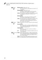
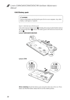
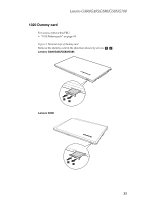
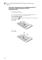
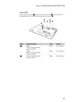
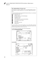
Lenovo G480/G485/G580/G585/G780 Removing and replacing an FRU This section presents exploded figures with the instructions to indicate how to remove and replace the FRU. Make sure to observe the following general rules: 1. Do not attempt to service any computer unless you have been trained and certified. An untrained person runs the risk of damaging parts. 2. Before replacing any FRU, review "FRU replacement notices" on page 32. 3. Begin by removing any FRUs that have to be removed before the failing FRU. Any of such FRUs are listed at the top of the page. Remove them in the order in which they are listed. 4. Follow the correct sequence in the steps to remove the FRU, as given in the figures by the numbers in square callouts. 5. When turning a screw to replace an FRU, turn it in the direction as given by the arrow in the figure. 6. When removing the FRU, move it in the direction as given by the arrow in the figure. 7. To put the new FRU in place, reverse the removal procedures and follow any of the notes that pertain to replacement. For information about connecting and arranging internal cables, see "Locations" on page 92. 8. When replacing an FRU, use the correct screw as shown in the procedures. DANGER Before removing any FRU, turn off the computer, unplug all power cords from electrical outlets, remove the battery pack, and then disconnect any of the interconnecting cables. Attention: After replacing an FRU, do not turn on the computer until you have made sure that all screws, springs, and other small parts are in place and none are loose inside the computer. Verify this by shaking the computer gently and listening for rattling sounds. Metallic parts or metal flakes can cause electrical short circuits. Attention: The system board is sensitive to, and can be damaged by, electrostatic discharge. Before touching it, establish personal grounding by touching a ground point with one hand or using an electrostatic discharge (ESD) strap (P/N 6405959) to remove potential shock reasons. Note: • The illustrations used in this section are of the Lenovo G580, unless otherwise stated. • The procedures listed below (for removing components) are the same for the Lenovo G480/G485/G580/G585/G780. • The illustrations in this manual may differ from the actual product. Please refer to the actual product. 33
-
 1
1 -
2
-
3
-
4
-
5
-
6
-
7
-
8
-
9
-
10
-
11
-
12
-
13
-
14
-
15
-
16
-
17
-
18
-
19
-
20
-
21
-
22
-
23
-
24
-
25
-
26
-
27
-
28
-
29
-
30
-
31
-
 32
32 -
 33
33 -
 34
34 -
 35
35 -
 36
36 -
 37
37 -
 38
38 -
 39
39 -
 40
40 -
 41
41 -
 42
42 -
43
-
44
-
45
-
46
-
47
-
48
-
49
-
50
-
51
-
52
-
53
-
54
-
55
-
56
-
57
-
58
-
59
-
60
-
61
-
62
-
63
-
64
-
65
-
66
-
67
-
68
-
69
-
70
-
71
-
72
-
73
-
74
-
75
-
76
-
77
-
78
-
79
-
80
-
81
-
82
-
83
-
84
-
85
-
86
-
87
-
88
-
89
-
90
-
91
-
92
-
93
-
94
-
95
-
96
-
97
-
98
-
99
-
100
-
101
-
102
-
103
-
104
-
105
-
106
-
107
-
108
-
109
-
110
-
111
-
112
-
113
-
114
-
115
-
116
-
117
-
118
-
119
-
120
-
121
-
122
-
123
-
124
 |
 |