Lenovo G510s Touch Hardware Maintenance Manual - Lenovo G410s Touch, G510s Tou - Page 72
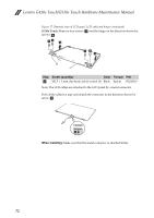
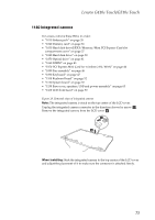
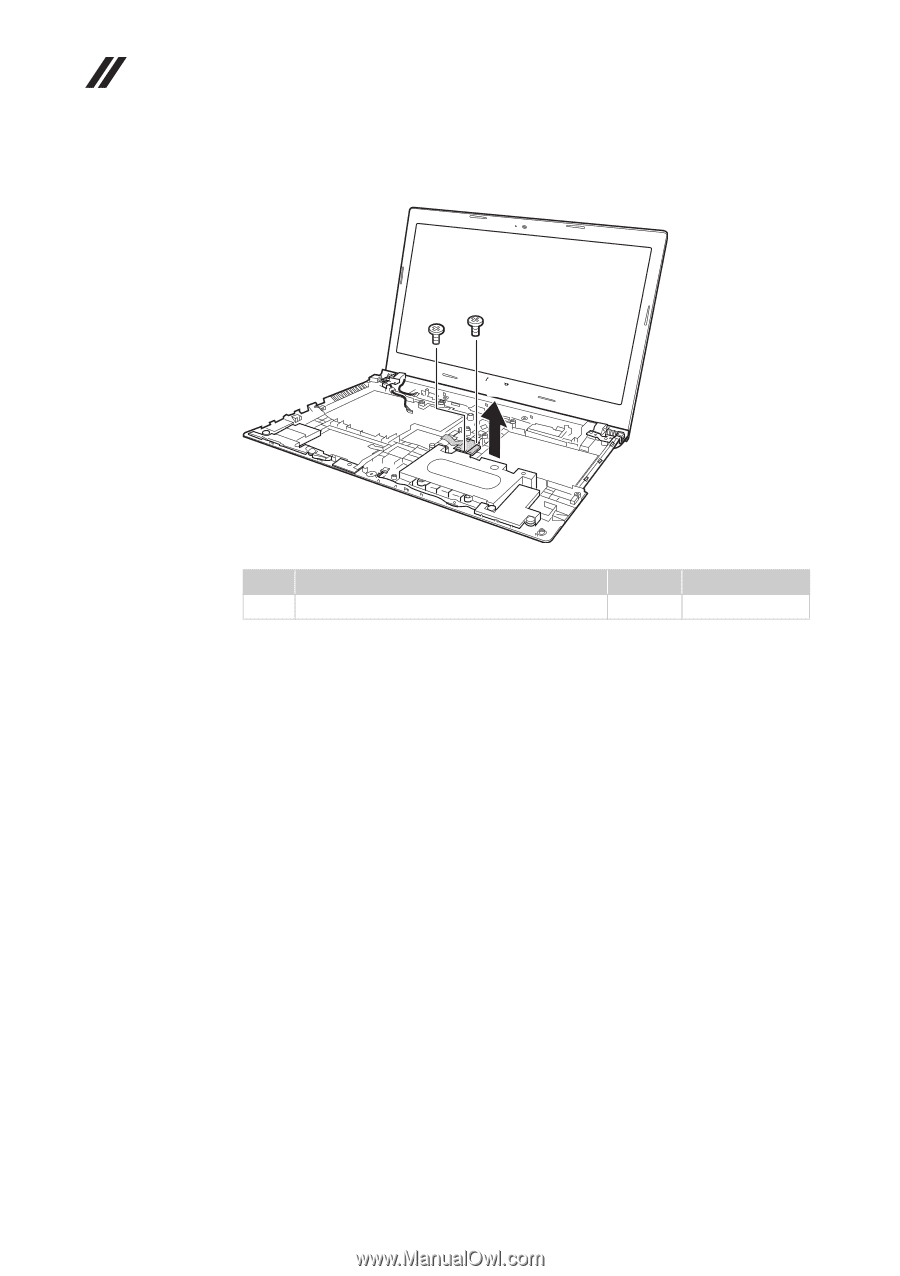
Remove screw, then remove LED board in the direction shown by arrow, M2.5 × 3 mm, flat-head, nylok-
 |
View all Lenovo G510s Touch manuals
Add to My Manuals
Save this manual to your list of manuals |
Page 72 highlights
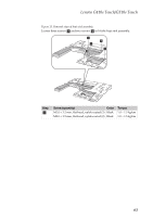
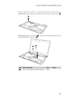
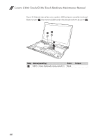
Lenovo G410s Touch/G510s Touch Hardware Maintenance Manual Figure 15. Removal steps of base cover, speakers, USB and power assembly (continued) Remove screw a, then remove LED board in the direction shown by arrow b. aa b Step Screw (quantity) Color a M2.5 × 3 mm, flat-head, nylok-coated (1) Black Torque 68
-
 1
1 -
2
-
3
-
4
-
5
-
6
-
7
-
8
-
9
-
10
-
11
-
12
-
13
-
14
-
15
-
16
-
17
-
18
-
19
-
20
-
21
-
22
-
23
-
24
-
25
-
26
-
27
-
28
-
29
-
30
-
31
-
32
-
33
-
34
-
35
-
36
-
37
-
38
-
39
-
40
-
41
-
42
-
43
-
44
-
45
-
46
-
47
-
48
-
49
-
50
-
51
-
52
-
53
-
54
-
55
-
56
-
57
-
58
-
59
-
60
-
61
-
62
-
63
-
64
-
65
-
66
-
 67
67 -
 68
68 -
 69
69 -
 70
70 -
 71
71 -
 72
72 -
 73
73 -
 74
74 -
 75
75 -
 76
76 -
 77
77 -
78
-
79
-
80
-
81
-
82
-
83
-
84
-
85
-
86
-
87
-
88
-
89
-
90
-
91
-
92
-
93
-
94
-
95
-
96
-
97
-
98
-
99
-
100
-
101
-
102
 |
 |
Lenovo G410s Touch/G510s Touch Hardware Maintenance Manual
68
Figure 15. Removal steps of base cover, speakers, USB and power assembly (continued)
Remove screw
, then remove LED board in the direction shown by arrow
.
Step
Screw (quantity)
Color
Torque
M2.5 × 3 mm, flat-head, nylok-coated (1)
Black
a
b
a
a
b
a