Lenovo G555 Laptop Lenovo G555 Hardware Maintenance Manual V2.0 - Page 53
Screw quantity, Color, Torque, Remove the screws
 |
View all Lenovo G555 Laptop manuals
Add to My Manuals
Save this manual to your list of manuals |
Page 53 highlights
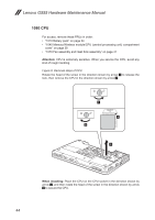
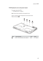
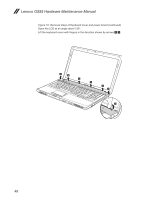
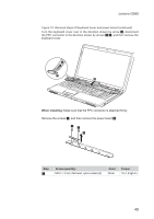
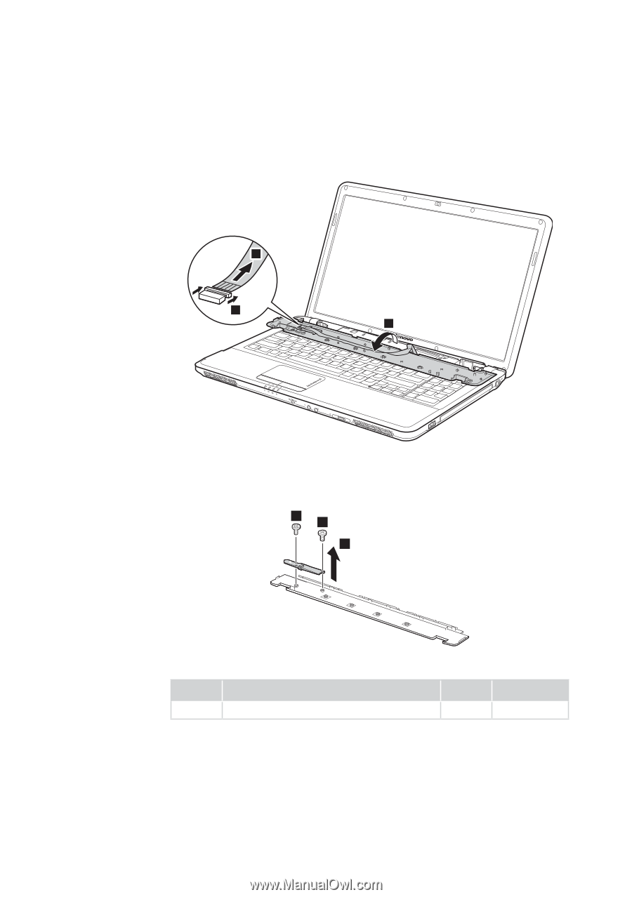
Lenovo G555 Figure 10. Removal steps of Keyboard cover and power board (continued) Turn the keyboard cover over in the direction shown by arrow 4, disconnect the FPC connector in the direction shown by arrows 5 6, and then remove the keyboard cover. 6 5 4 When installing: Make sure that the FPC connector is attached firmly. Remove the screws 7, and then remove the power board 8. 7 7 8 Step 7 Screw (quantity) M2.0 × 3 mm, flat-head, nylon-coated (2) Color Silver Torque 1.0~1.5 kgf·cm 49
-
 1
1 -
2
-
3
-
4
-
5
-
6
-
7
-
8
-
9
-
10
-
11
-
12
-
13
-
14
-
15
-
16
-
17
-
18
-
19
-
20
-
21
-
22
-
23
-
24
-
25
-
26
-
27
-
28
-
29
-
30
-
31
-
32
-
33
-
34
-
35
-
36
-
37
-
38
-
39
-
40
-
41
-
42
-
43
-
44
-
45
-
46
-
47
-
 48
48 -
 49
49 -
 50
50 -
 51
51 -
 52
52 -
 53
53 -
 54
54 -
 55
55 -
 56
56 -
 57
57 -
 58
58 -
59
-
60
-
61
-
62
-
63
-
64
-
65
-
66
-
67
-
68
-
69
-
70
-
71
-
72
-
73
-
74
-
75
-
76
-
77
-
78
-
79
-
80
-
81
-
82
-
83
-
84
-
85
-
86
-
87
-
88
-
89
-
90
-
91
-
92
 |
 |
49
Lenovo G555
Figure 10. Removal steps of Keyboard cover and power board (continued)
Turn the keyboard cover over in the direction shown by arrow
4
, disconnect
the FPC connector in the direction shown by arrows
5
6
, and then remove the
keyboard cover.
6
5
4
When installing:
Make sure that the FPC connector is attached firmly.
Remove the screws
7
, and then remove the power board
8
.
8
7
7
Step
Screw (quantity)
Color
Torque
7
M2.0 × 3 mm, flat-head, nylon-coated (2)
Silver
1.0~1.5 kgf·cm