Lenovo G70-70 Laptop Hardware Maintenance Manual - Lenovo G70-70 - Page 71
M2.0 × 3 mm, flat-head, nylok-coated 2
 |
View all Lenovo G70-70 Laptop manuals
Add to My Manuals
Save this manual to your list of manuals |
Page 71 highlights
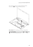
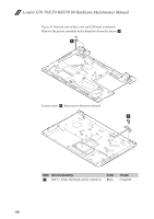
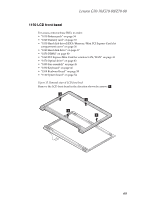
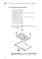
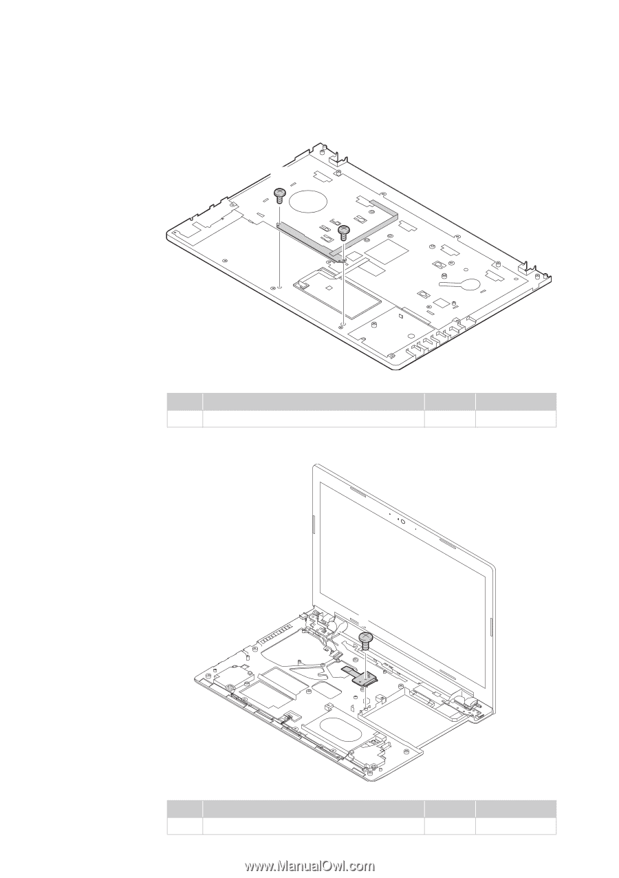
Lenovo G70-70/G70-80/Z70-80 Figure 14. Removal steps of base cover and LED board (continued) Loosen the two screws a, then remove the LED board. a a Step Screw (quantity) a M2.0 × 3 mm, flat-head, nylok-coated (2) Color Black Torque 2.0 kgfcm Loosen screw a, then remove the optical disk drive switch board. a Step Screw (quantity) a M2.5 × 4 mm, flat-head, nylok-coated (1) Color Black Torque 3.0 kgfcm 67
-
 1
1 -
2
-
3
-
4
-
5
-
6
-
7
-
8
-
9
-
10
-
11
-
12
-
13
-
14
-
15
-
16
-
17
-
18
-
19
-
20
-
21
-
22
-
23
-
24
-
25
-
26
-
27
-
28
-
29
-
30
-
31
-
32
-
33
-
34
-
35
-
36
-
37
-
38
-
39
-
40
-
41
-
42
-
43
-
44
-
45
-
46
-
47
-
48
-
49
-
50
-
51
-
52
-
53
-
54
-
55
-
56
-
57
-
58
-
59
-
60
-
61
-
62
-
63
-
64
-
65
-
 66
66 -
 67
67 -
 68
68 -
 69
69 -
 70
70 -
 71
71 -
 72
72 -
 73
73 -
 74
74 -
 75
75 -
 76
76 -
77
-
78
-
79
-
80
-
81
-
82
-
83
-
84
-
85
-
86
-
87
-
88
-
89
-
90
-
91
-
92
-
93
-
94
-
95
-
96
-
97
-
98
-
99
-
100
-
101
-
102
-
103
-
104
-
105
-
106
-
107
 |
 |
Lenovo G70-70/G70-80/Z70-80
67
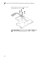
Figure 14. Removal steps of base cover and LED board (continued)
Loosen the two screws
, then remove the LED board.
Loosen screw
, then remove the optical disk drive switch board.
Step
Screw (quantity)
Color
Torque
M2.0 × 3 mm, flat-head, nylok-coated (2)
Black
2.0 kgfcm
Step
Screw (quantity)
Color
Torque
M2.5 × 4 mm, flat-head, nylok-coated (1)
Black
3.0 kgfcm
a
a
a
a
a
a
a