Lenovo G700 Hardware Maintenance Manual - Lenovo G700, G710 - Page 48
Fan assembly and Heat Sink assembly
 |
View all Lenovo G700 manuals
Add to My Manuals
Save this manual to your list of manuals |
Page 48 highlights
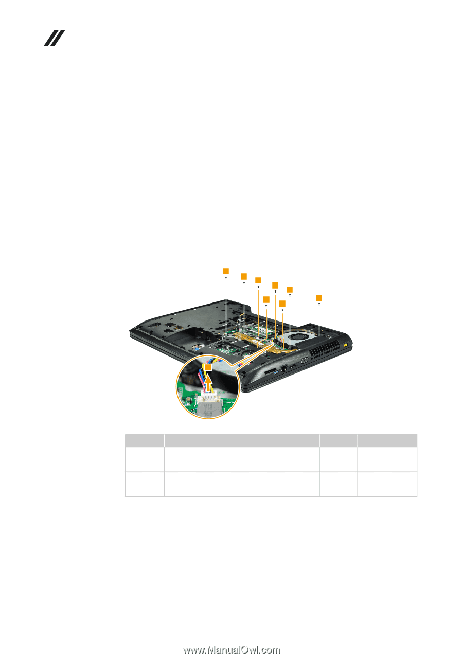
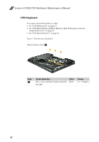
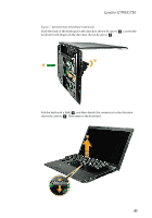
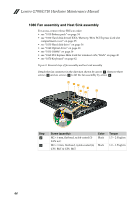
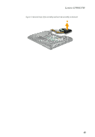
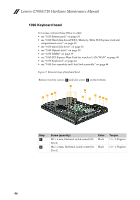
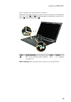
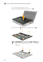
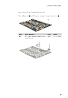
Lenovo G700/G710 Hardware Maintenance Manual 1080 Fan assembly and Heat Sink assembly For access, remove these FRUs in order: • see "1010 Battery pack" on page 34 • see "1020 Hard disk drive(HDD)/Memory/Mini PCI Express Card slot compartment cover" on page 35 • see "1030 Hard disk drive" on page 36 • see "1040 Optical drive" on page 38 • see "1050 DIMM" on page 39 • see "1060 PCI Express Mini Card for wireless LAN/WAN" on page 40 • see "1070 Keyboard" on page 42 Figure 8. Removal steps of fan assembly and heat sink assembly Detach the fan connector in the direction shown by arrow a. Remove three screws b and six screws c to lift the fan assembly by arrow d. 3 3 3 2 2 3 2 3 1 Step b d c Screw (quantity) M2 × 6 mm, flat-head, nylok-coated (3) FAN to C M2 × 3 mm, flat-head, nylok-coated (6) CPU BKT & GPU BKT Color Black Black Torque 1.5 ~ 2.0 kgfcm 1.0 ~ 1.5 kgfcm 44
-
 1
1 -
2
-
3
-
4
-
5
-
6
-
7
-
8
-
9
-
10
-
11
-
12
-
13
-
14
-
15
-
16
-
17
-
18
-
19
-
20
-
21
-
22
-
23
-
24
-
25
-
26
-
27
-
28
-
29
-
30
-
31
-
32
-
33
-
34
-
35
-
36
-
37
-
38
-
39
-
40
-
41
-
42
-
 43
43 -
 44
44 -
 45
45 -
 46
46 -
 47
47 -
 48
48 -
 49
49 -
 50
50 -
 51
51 -
 52
52 -
 53
53 -
54
-
55
-
56
-
57
-
58
-
59
-
60
-
61
-
62
-
63
-
64
-
65
-
66
-
67
-
68
-
69
-
70
-
71
-
72
-
73
-
74
-
75
-
76
-
77
-
78
-
79
-
80
-
81
-
82
-
83
-
84
-
85
-
86
-
87
-
88
 |
 |