Lenovo G770 Lenovo G770 Hardware Maintenance Manual V1.0 - Page 65
LCD panel, LCD cable and hinges
 |
View all Lenovo G770 manuals
Add to My Manuals
Save this manual to your list of manuals |
Page 65 highlights
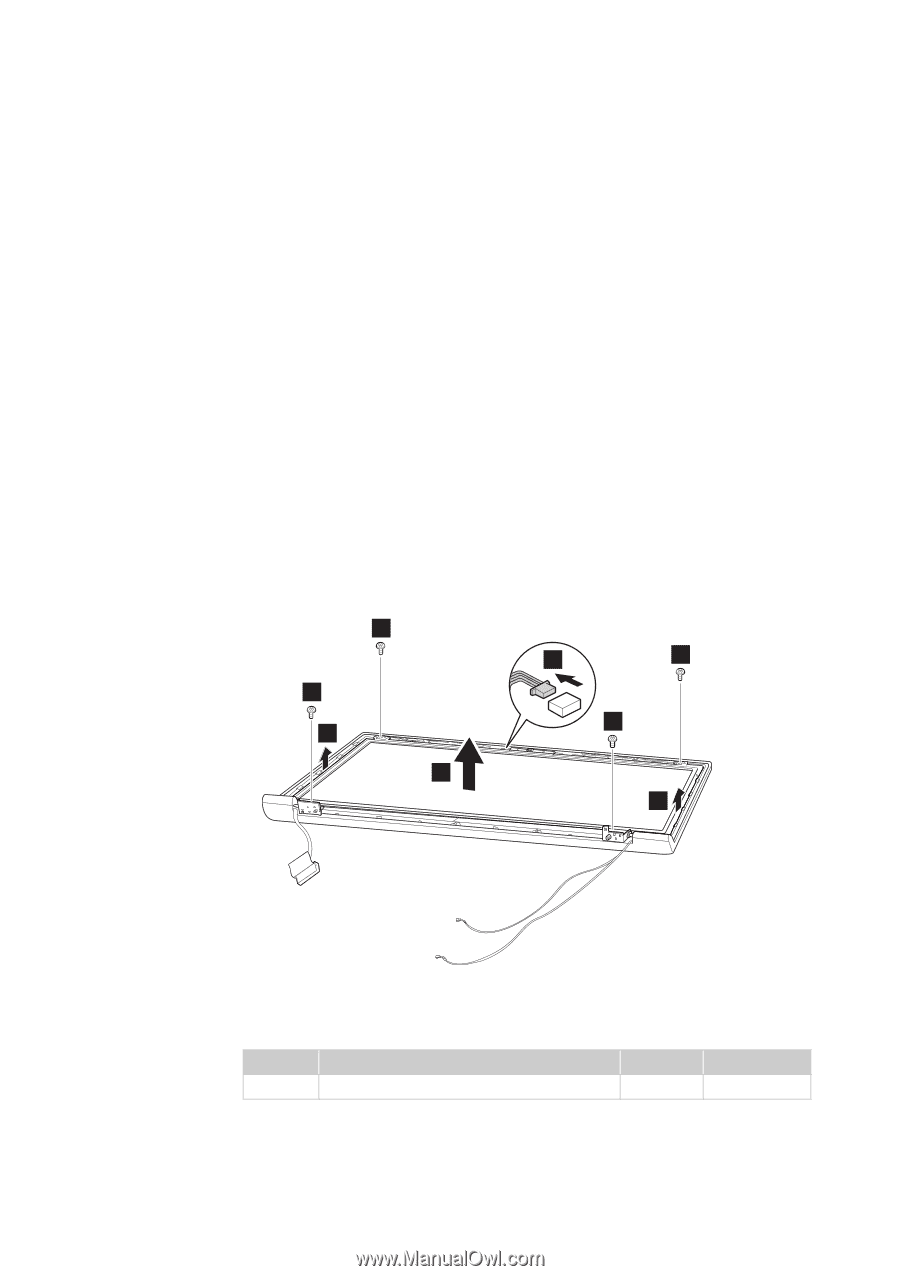
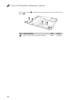
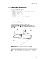
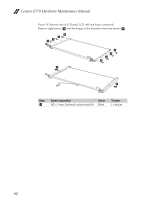
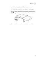
Lenovo G770 1160 LCD panel, LCD cable and hinges For access, remove these FRUs in order: • "1010 Battery pack" on page 34 • "1030 Hard disk drive(HDD)/Memory/Mini PCI Express Card slot compartment cover" on page 36 • "1040 Hard disk drive" on page 37 • "1050 Optical drive" on page 39 • "1060 DIMM" on page 40 • "1070 PCI Express Mini Card for wireless LAN/WAN" on page 41 • "1080 Keyboard" on page 43 • "1090 Keyboard bezel" on page 45 • "1100 System board" on page 49 • "1110 LCD unit" on page 52 • "1150 LCD front bezel" on page 60 Figure 16. Removal steps of LCD panel, LCD cable and hinges Remove four screws a. Unplug the integrated camera connector in the direction shown by arrow b. Lift the LCD panel in the direction shown by arrows c. 1 2 1 1 1 3 3 3 When installing: Make sure that the connector is attached firmly. Step a Screw (quantity) Color M2.5 × 4 mm, flat-head, nylok-coated (4) Black Torque 2.0 kgfcm 61
-
 1
1 -
2
-
3
-
4
-
5
-
6
-
7
-
8
-
9
-
10
-
11
-
12
-
13
-
14
-
15
-
16
-
17
-
18
-
19
-
20
-
21
-
22
-
23
-
24
-
25
-
26
-
27
-
28
-
29
-
30
-
31
-
32
-
33
-
34
-
35
-
36
-
37
-
38
-
39
-
40
-
41
-
42
-
43
-
44
-
45
-
46
-
47
-
48
-
49
-
50
-
51
-
52
-
53
-
54
-
55
-
56
-
57
-
58
-
59
-
 60
60 -
 61
61 -
 62
62 -
 63
63 -
 64
64 -
 65
65 -
 66
66 -
 67
67 -
 68
68 -
 69
69 -
 70
70 -
71
-
72
-
73
-
74
-
75
-
76
-
77
-
78
-
79
-
80
-
81
-
82
-
83
-
84
-
85
-
86
-
87
-
88
-
89
 |
 |