Lenovo IdeaCentre A530 IdeaCentre A530 All-In-One PC Hardware Maintenance Manu - Page 64
Replacing the converter board
 |
View all Lenovo IdeaCentre A530 manuals
Add to My Manuals
Save this manual to your list of manuals |
Page 64 highlights
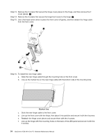
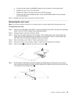
Step 8. Lift up the touch control board to remove it from the middle frame. Step 9. To install the new touch control board: a. Connect all the cables to the new touch control board. b. Remove the insulating paper (siliconed paper) of the double sided tape on the new touch control board. c. Line up the new touch control board with the mounting marks on the middle frame, then stick it to the middle frame. Step 10. Reattach the rear cover to the LED panel. Step 11. Reattach the hinge to the chassis, and reconnect the scalar headphone input, scalar and DVI/HDMI cables to the motherboard. Step 12. Reattach the base cover and secure it with the screws. Replacing the converter board Note: Turn off the computer and wait 3 to 5 minutes to let it cool down before removing the base cover. To replace the converter board: Step 1. Step 2. Step 3. Step 4. Step 5. Remove any media (disks, CDs, DVDs, or memory cards) from the drives, shut down the operating system, and turn off the computer and all attached devices. Unplug all power cords from electrical outlets. Disconnect all cables attached to the computer. This includes power cords, input/output (I/O) cables, and any other cables that are connected to the computer. Refer to "Left and right view" and "Rear view" for help with locating the various connectors. Remove the base cover. Refer to "Removing the base cover". Remove the hinge from the chassis. Refer to "Removing the hinge from the chassis". 58 IdeaCentre A530 All-In-One PC Hardware Maintenance Manual
-
 1
1 -
2
-
3
-
4
-
5
-
6
-
7
-
8
-
9
-
10
-
11
-
12
-
13
-
14
-
15
-
16
-
17
-
18
-
19
-
20
-
21
-
22
-
23
-
24
-
25
-
26
-
27
-
28
-
29
-
30
-
31
-
32
-
33
-
34
-
35
-
36
-
37
-
38
-
39
-
40
-
41
-
42
-
43
-
44
-
45
-
46
-
47
-
48
-
49
-
50
-
51
-
52
-
53
-
54
-
55
-
56
-
57
-
58
-
 59
59 -
 60
60 -
 61
61 -
 62
62 -
 63
63 -
 64
64 -
 65
65 -
 66
66 -
 67
67 -
 68
68 -
 69
69 -
70
-
71
-
72
-
73
 |
 |
