Lenovo IdeaPad S205 Lenovo IdeaPad S205 Hardware Maintenance Manual - Page 52
Fan assembly and heat sink assembly
 |
View all Lenovo IdeaPad S205 manuals
Add to My Manuals
Save this manual to your list of manuals |
Page 52 highlights
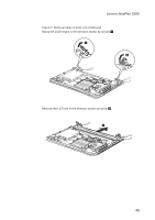
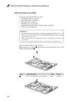
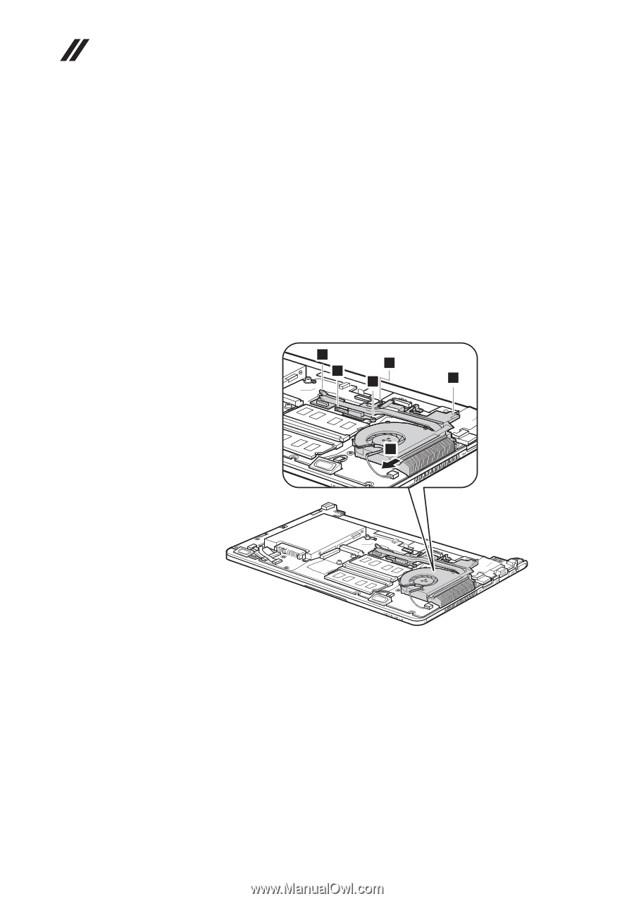
IdeaPad S205 Hardware Maintenance Manual 1100 Fan assembly and heat sink assembly For access, remove this FRU: •• "1010 Battery pack" on page 34 •• "1020 Dummy card" on page 35 •• "1040 Keyboard" on page 37 •• "1050 Base cover" on page 39 •• "1060 PCI Express Mini Card for wireless LAN" on page 42 •• "1070 LCD unit" on page 44 Figure 10. Removal steps of fan assembly and heat sink assembly Note: Loosen five screws 1, but do not remove them. Detach the fan connector in the direction shown by arrow 2. 1 1 1 1 1 2 When installing: Make sure that the fan connector is attached firmly to the system board. 48
-
 1
1 -
2
-
3
-
4
-
5
-
6
-
7
-
8
-
9
-
10
-
11
-
12
-
13
-
14
-
15
-
16
-
17
-
18
-
19
-
20
-
21
-
22
-
23
-
24
-
25
-
26
-
27
-
28
-
29
-
30
-
31
-
32
-
33
-
34
-
35
-
36
-
37
-
38
-
39
-
40
-
41
-
42
-
43
-
44
-
45
-
46
-
 47
47 -
 48
48 -
 49
49 -
 50
50 -
 51
51 -
 52
52 -
 53
53 -
 54
54 -
 55
55 -
 56
56 -
 57
57 -
58
-
59
-
60
-
61
-
62
-
63
-
64
-
65
-
66
-
67
-
68
-
69
-
70
-
71
-
72
-
73
-
74
-
75
-
76
-
77
-
78
-
79
-
80
-
81
 |
 |
48
IdeaPad S205 Hardware Maintenance Manual
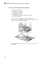
1100 Fan assembly and heat sink assembly
For access, remove this FRU:
•
“1010 Battery pack” on page 34
•
“1020 Dummy card” on page 35
•
“1040 Keyboard” on page 37
•
“1050 Base cover” on page 39
•
“1060 PCI Express Mini Card for wireless LAN” on page 42
•
“1070 LCD unit” on page 44
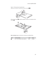
Figure 10. Removal steps of fan assembly and heat sink assembly
Note:
Loosen five screws
1
, but do not remove them. Detach the fan
connector in the direction shown by arrow
2
.
1
1
1
1
1
2
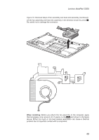
When installing:
Make sure that the fan connector is attached firmly to the
system board.