Lenovo IdeaPad S205s Lenovo IdeaPad S205s Hardware Maintenance Manual - Page 53
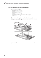
part shown in the figure, Removal steps of fan assembly and heat sink assembly continued
 |
View all Lenovo IdeaPad S205s manuals
Add to My Manuals
Save this manual to your list of manuals |
Page 53 highlights
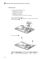
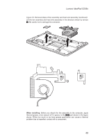
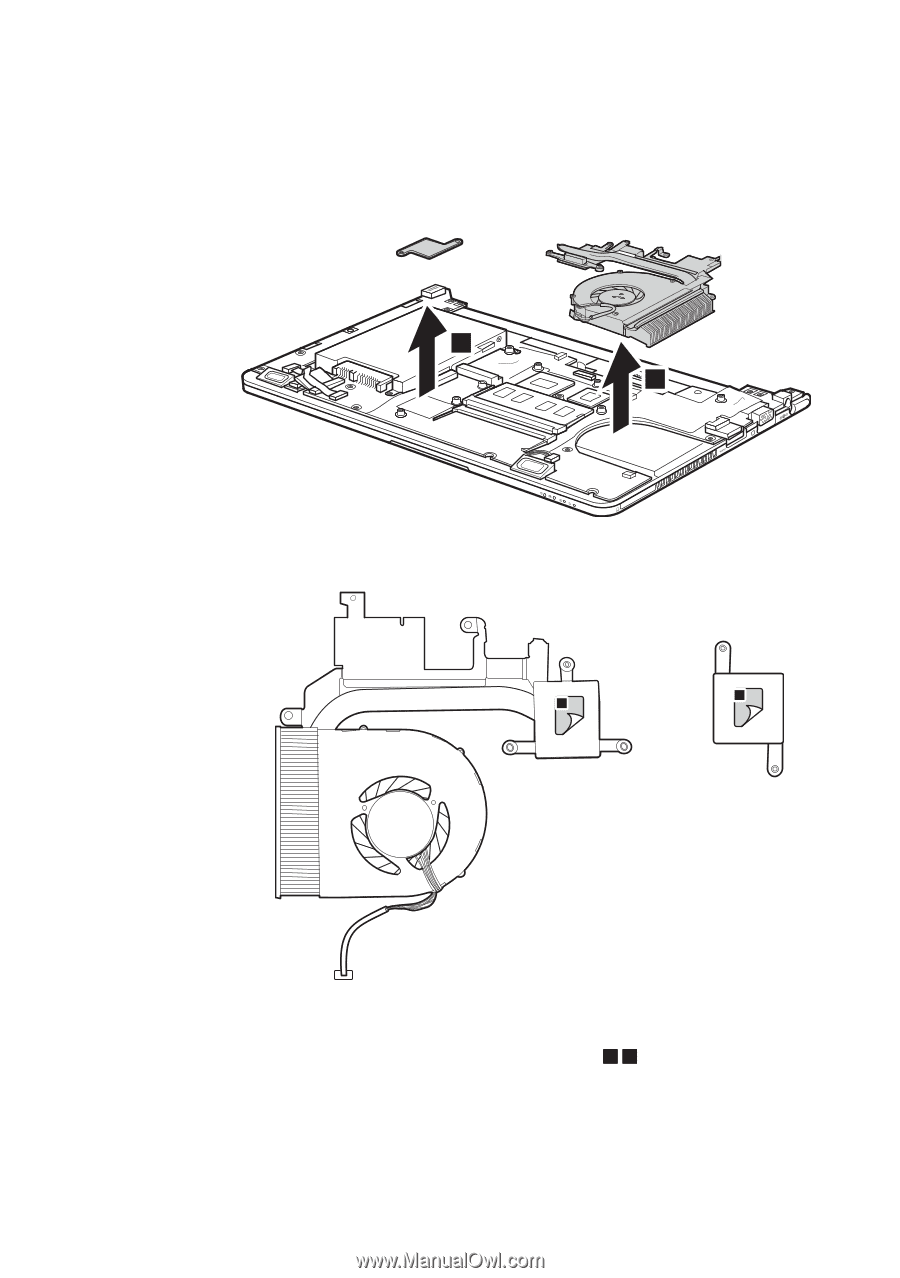
Lenovo IdeaPad S205s Figure 10. Removal steps of fan assembly and heat sink assembly (continued) Lift the fan assembly and heat sink assembly in the direction shown by arrows 3. Be careful not to damage the connector. 3 3 b a When installing: Before you attach the fan assembly to the computer, apply thermal grease, at an amount of 0.2 grams, to the a b part shown in the figure above. Either too much or too less grease application can cause a thermal problem due to imperfect contact with a component. 49
-
 1
1 -
2
-
3
-
4
-
5
-
6
-
7
-
8
-
9
-
10
-
11
-
12
-
13
-
14
-
15
-
16
-
17
-
18
-
19
-
20
-
21
-
22
-
23
-
24
-
25
-
26
-
27
-
28
-
29
-
30
-
31
-
32
-
33
-
34
-
35
-
36
-
37
-
38
-
39
-
40
-
41
-
42
-
43
-
44
-
45
-
46
-
47
-
 48
48 -
 49
49 -
 50
50 -
 51
51 -
 52
52 -
 53
53 -
 54
54 -
 55
55 -
 56
56 -
 57
57 -
 58
58 -
59
-
60
-
61
-
62
-
63
-
64
-
65
-
66
-
67
-
68
-
69
-
70
-
71
-
72
-
73
-
74
-
75
-
76
-
77
-
78
-
79
 |
 |
49
Lenovo IdeaPad S205s
Figure 10. Removal steps of fan assembly and heat sink assembly (continued)
Lift the fan assembly and heat sink assembly in the direction shown by arrows
3
. Be careful not to damage the connector.
3
3
a
b
When installing:
Before you attach the fan assembly to the computer, apply
thermal grease, at an amount of 0.2 grams, to the
a
b
part shown in the figure
above. Either too much or too less grease application can cause a thermal
problem due to imperfect contact with a component.