Lenovo IdeaPad S215 Hardware Maintenance Manual - IdeaPad S210, S210 Touch, S2 - Page 63
Antenna assembly and LCD cover
 |
View all Lenovo IdeaPad S215 manuals
Add to My Manuals
Save this manual to your list of manuals |
Page 63 highlights
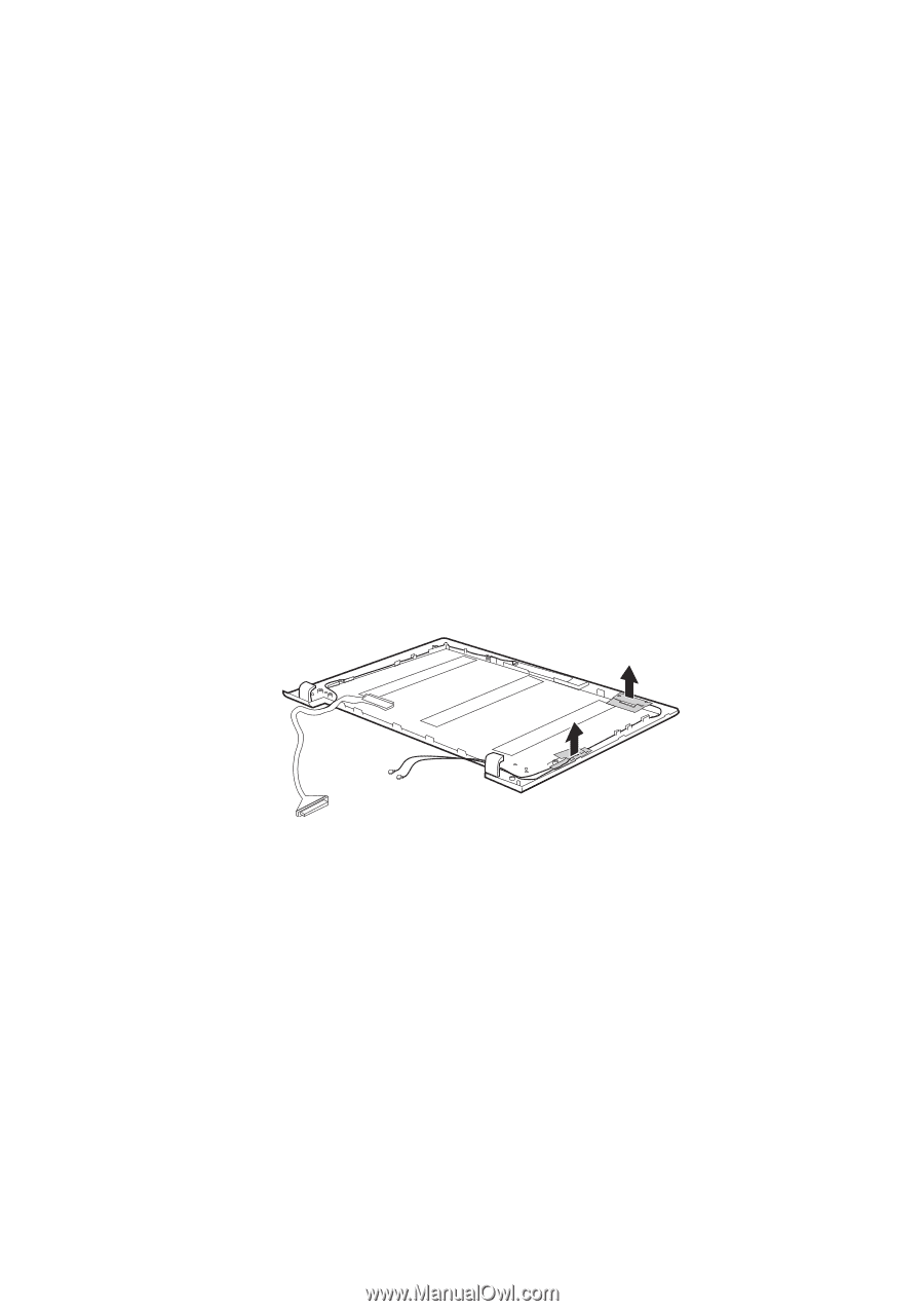
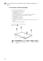
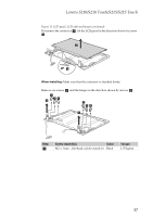
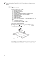
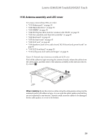
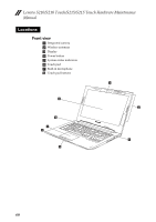
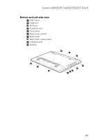
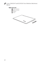
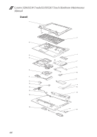
Lenovo S210/S210 Touch/S215/S215 Touch 1130 Antenna assembly and LCD cover For access, remove these FRUs in order: • "1010 Battery pack" on page 34 • "1020 Hard disk drive" on page 36 • "1030 DIMM" on page 38 • "1040 PCI Express Mini Card for wireless LAN/WAN" on page 39 • "1050 Fan assembly and Heat Sink assembly" on page 41 • "1060 Keyboard" on page 43 • "1070 System board" on page 45 • "1080 LCD unit" on page 49 • "1090 Speakers, base cover, audio board, DC-IN board and power board" on page 51 • "1100 LCD front bezel" on page 55 • "1110 LCD panel, LCD cable and hinges" on page 56 Figure 13. Removal steps of antenna assembly and LCD cover Peel off the adhesive tapes securing the antenna boards, release the cables from the cable guide, and then remove the antenna assembly in the direction shown by arrows a. a a When installing: Route the antenna cables along the cable guides and secure the antenna boards with adhesive tapes. As you route the cables, make sure that they are not subjected to any tension. Tension could cause the cables to be damaged by the cable guides, or a wire to be broken. 59
-
 1
1 -
2
-
3
-
4
-
5
-
6
-
7
-
8
-
9
-
10
-
11
-
12
-
13
-
14
-
15
-
16
-
17
-
18
-
19
-
20
-
21
-
22
-
23
-
24
-
25
-
26
-
27
-
28
-
29
-
30
-
31
-
32
-
33
-
34
-
35
-
36
-
37
-
38
-
39
-
40
-
41
-
42
-
43
-
44
-
45
-
46
-
47
-
48
-
49
-
50
-
51
-
52
-
53
-
54
-
55
-
56
-
57
-
 58
58 -
 59
59 -
 60
60 -
 61
61 -
 62
62 -
 63
63 -
 64
64 -
 65
65 -
 66
66 -
 67
67 -
 68
68 -
69
-
70
-
71
-
72
-
73
-
74
-
75
-
76
-
77
-
78
-
79
-
80
-
81
-
82
-
83
-
84
-
85
-
86
-
87
-
88
-
89
-
90
 |
 |