Lenovo IdeaPad Z560 Lenovo IdeaPad Z560/Z565 Hardware Maintenance Manual - Page 58
System board and ExpressCard slot assembly, Important notices for handling the system board - lcd front bezel
 |
View all Lenovo IdeaPad Z560 manuals
Add to My Manuals
Save this manual to your list of manuals |
Page 58 highlights
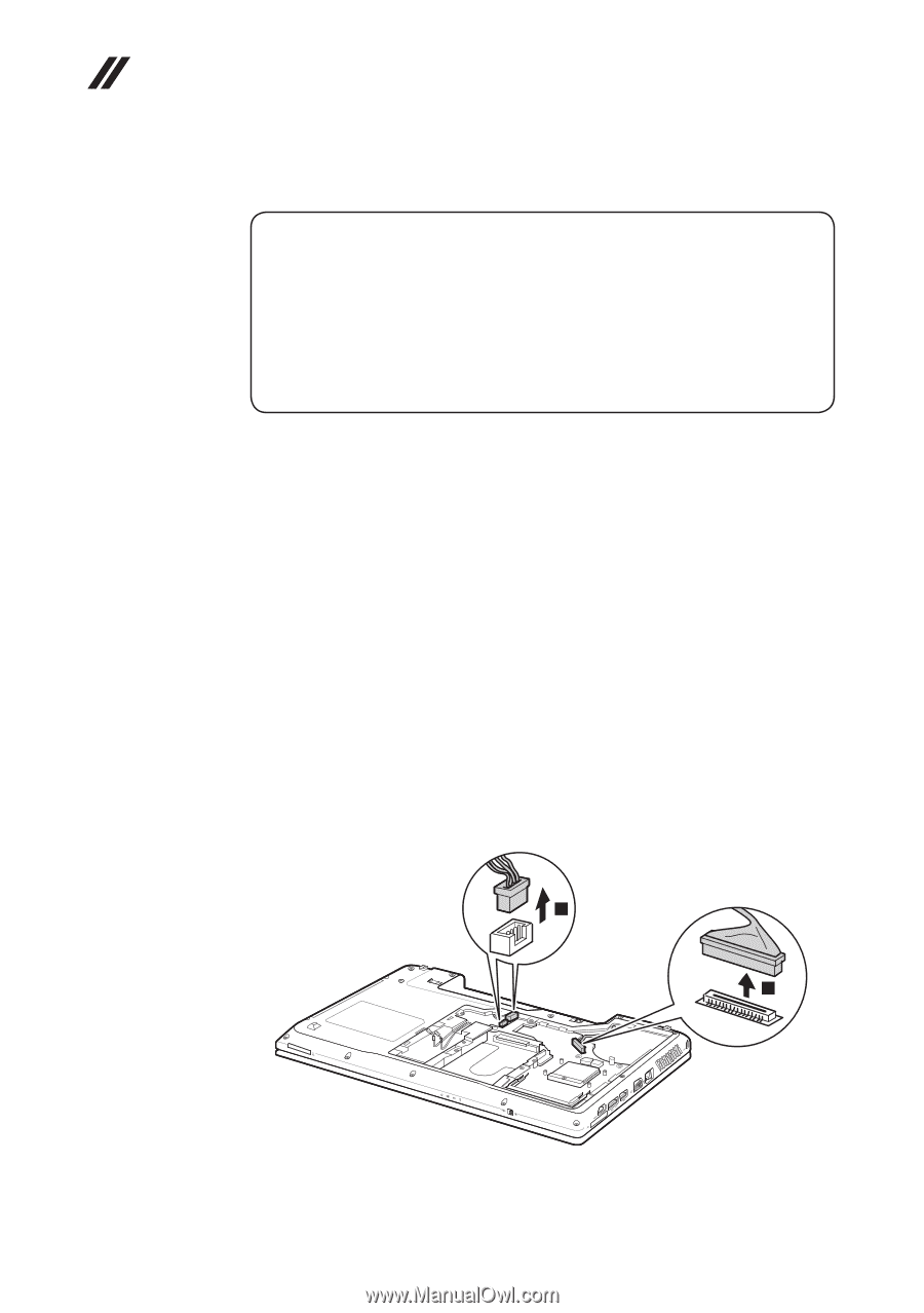
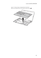
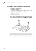
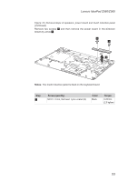
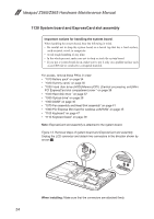
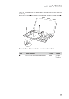
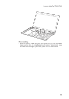
Ideapad Z560/Z565 Hardware Maintenance Manual 1130 System board and ExpressCard slot assembly Important notices for handling the system board: When handling the system board, bear the following in mind. • Be careful not to drop the system board on a bench top that has a hard surface, such as metal, wood, or composite. • Avoid rough handling of any kind. • In the whole process, make sure not to drop or stack the system board. • If you put a system board down, make sure to put it only on a padded surface such as an ESD mat or conductive corrugated material. For access, remove these FRUs in order: •• "1010 Battery pack" on page 34 •• "1020 Dummy cards" on page 35 •• "1030 Hard disk drive (HDD)/Memory/CPU (Central processing unit)/Mini PCI ExpressCard slot compartment cover " on page 36 •• "1040 Hard disk drive " on page 37 •• "1050 Optical drive" on page 39 •• "1060 DIMM" on page 40 •• "1070 Fan assembly and Heat Sink assembly" on page 41 •• "1090 PCI Express Mini Card for wireless LAN/WAN" on page 45 •• "1100 Keyboard" on page 47 •• "1110 Keyboard bezel" on page 49 Note: ExpressCard slot assembly is attached to the system board. Figure 13. Removal steps of system board and ExpressCard slot assembly Unplug the LCD connector and detach two connectors in the direction shown by arrows 1. 1 1 When installing: Make sure that the connectors are attached firmly. 54
-
 1
1 -
2
-
3
-
4
-
5
-
6
-
7
-
8
-
9
-
10
-
11
-
12
-
13
-
14
-
15
-
16
-
17
-
18
-
19
-
20
-
21
-
22
-
23
-
24
-
25
-
26
-
27
-
28
-
29
-
30
-
31
-
32
-
33
-
34
-
35
-
36
-
37
-
38
-
39
-
40
-
41
-
42
-
43
-
44
-
45
-
46
-
47
-
48
-
49
-
50
-
51
-
52
-
 53
53 -
 54
54 -
 55
55 -
 56
56 -
 57
57 -
 58
58 -
 59
59 -
 60
60 -
 61
61 -
 62
62 -
 63
63 -
64
-
65
-
66
-
67
-
68
-
69
-
70
-
71
-
72
-
73
-
74
-
75
-
76
-
77
-
78
-
79
-
80
-
81
-
82
-
83
-
84
-
85
-
86
-
87
-
88
-
89
-
90
 |
 |