Lenovo J115 Hardware Maintenance Manual - Page 88
Replacing the microprocessor (Types 7393
 |
View all Lenovo J115 manuals
Add to My Manuals
Save this manual to your list of manuals |
Page 88 highlights
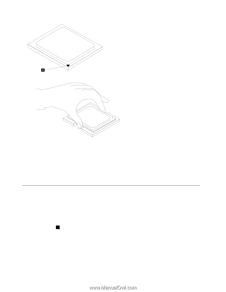
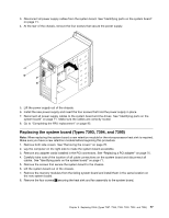
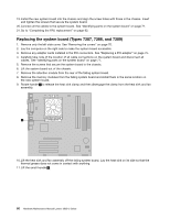
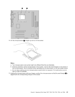
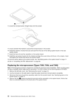
14. Lower the microprocessor straight down into the socket. 15. Lower and latch the handle to secure the microprocessor in the socket. 16. Install the retention module that was removed from the rear of the failing system board on the new system board. 17. Install the heat sink and fan assembly on the system board. 18. Install the new system board into the chassis and align the screw holes with those in the chassis. Insert and tighten the screws that secure the system board. 19. Connect all the cables to the system board. See "Identifying parts on the system board" on page 71. 20. Go to "Completing the FRU replacement" on page 92. Replacing the microprocessor (Types 7393, 7394, and 7395) Note: A thermal grease syringe is required to complete the microprocessor installation. Make sure the grease syringe is available before beginning the procedure. The FRU number for the thermal grease is 91P8835. 1. Remove the left-side cover. See "Removing the covers" on page 70. 2. Lay the computer on the right side to make the system board and microprocessor accessible. 3. Disconnect the heat sink and fan assembly cable from the system board. See "Identifying parts on the system board" on page 71. 4. Remove the four 1 screws securing the heat sink and fan assembly to the system board. Notice that there is a retention bracket on the back side of the system board. 82 Hardware Maintenance Manual Lenovo 3000 J Series
-
 1
1 -
2
-
3
-
4
-
5
-
6
-
7
-
8
-
9
-
10
-
11
-
12
-
13
-
14
-
15
-
16
-
17
-
18
-
19
-
20
-
21
-
22
-
23
-
24
-
25
-
26
-
27
-
28
-
29
-
30
-
31
-
32
-
33
-
34
-
35
-
36
-
37
-
38
-
39
-
40
-
41
-
42
-
43
-
44
-
45
-
46
-
47
-
48
-
49
-
50
-
51
-
52
-
53
-
54
-
55
-
56
-
57
-
58
-
59
-
60
-
61
-
62
-
63
-
64
-
65
-
66
-
67
-
68
-
69
-
70
-
71
-
72
-
73
-
74
-
75
-
76
-
77
-
78
-
79
-
80
-
81
-
82
-
 83
83 -
 84
84 -
 85
85 -
 86
86 -
 87
87 -
 88
88 -
 89
89 -
 90
90 -
 91
91 -
 92
92 -
 93
93 -
94
-
95
-
96
-
97
-
98
-
99
-
100
-
101
-
102
-
103
-
104
-
105
-
106
-
107
-
108
-
109
-
110
-
111
-
112
-
113
-
114
-
115
-
116
-
117
-
118
-
119
-
120
-
121
-
122
-
123
-
124
-
125
-
126
-
127
-
128
-
129
-
130
-
131
-
132
-
133
-
134
-
135
-
136
-
137
-
138
-
139
-
140
-
141
-
142
-
143
-
144
-
145
-
146
-
147
-
148
-
149
-
150
-
151
-
152
-
153
-
154
-
155
-
156
-
157
-
158
-
159
-
160
-
161
-
162
-
163
-
164
-
165
-
166
-
167
-
168
-
169
-
170
-
171
-
172
-
173
-
174
-
175
-
176
-
177
-
178
-
179
-
180
-
181
-
182
-
183
-
184
-
185
-
186
-
187
-
188
-
189
-
190
-
191
-
192
-
193
-
194
-
195
-
196
-
197
-
198
-
199
-
200
 |
 |