Lenovo Miix 2 8 Hardware Maintenance Manual - Lenovo Miix 2 8 - Page 42
Removal steps of system board, Then remove the screw - gps
 |
View all Lenovo Miix 2 8 manuals
Add to My Manuals
Save this manual to your list of manuals |
Page 42 highlights
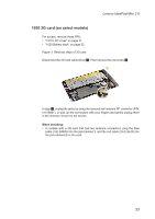
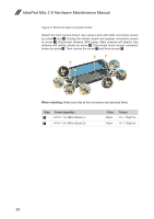
IdeaPad Miix 2 8 Hardware Maintenance Manual Figure 5. Removal steps of system board Detach the front camera board, rear camera and LCD cable connectors shown by arrow 1 and 2. Unplug the vibrator board and speaker connectors shown by arrow 3. Disconnect antenna GPS (gray), Main antenna wifi (black), Aux antenna wifi (white) shown by arrow 4. Disconnect touch screen connector shown by arrow 5. Then remove the screw 7 and three screws 6. 6 6 3 1 7 66 1 2 5 2 4 1 3 2 When installing: Make sure that all the connectors are attached firmly. Step 5 6 Screw (quantity) M1.6 × 1.6, MB to Bezel (1) M1.6 × 3.0, MB to Bezel (3) Color Black Black Torque 1.0 ~ 1.5kgf*cm 1.0 ~ 1.5kgf*cm 38
-
 1
1 -
2
-
3
-
4
-
5
-
6
-
7
-
8
-
9
-
10
-
11
-
12
-
13
-
14
-
15
-
16
-
17
-
18
-
19
-
20
-
21
-
22
-
23
-
24
-
25
-
26
-
27
-
28
-
29
-
30
-
31
-
32
-
33
-
34
-
35
-
36
-
 37
37 -
 38
38 -
 39
39 -
 40
40 -
 41
41 -
 42
42 -
 43
43 -
 44
44 -
 45
45 -
 46
46 -
 47
47 -
48
-
49
-
50
-
51
-
52
-
53
-
54
-
55
-
56
-
57
 |
 |

38
IdeaPad Miix 2 8 Hardware Maintenance Manual
Figure 5. Removal steps of system board
Detach the front camera board, rear camera and LCD cable connectors shown
by arrow
1
and
2
. Unplug the vibrator board and speaker connectors shown
by arrow
3
. Disconnect antenna GPS (gray), Main antenna wifi (black), Aux
antenna wifi (white) shown by arrow
4
. Disconnect touch screen connector
shown by arrow
5
. Then remove the screw
7
and three screws
6
.
4
1
2
1
2
5
1
2
7
6
6
3
3
6
When installing:
Make sure that all the connectors are attached firmly.
Step
Screw (quantity)
Color
Torque
5
M1.6 × 1.6, MB to Bezel (1)
Black
1.0 ~ 1.5kgf*cm
6
M1.6 × 3.0, MB to Bezel (3)
Black
1.0 ~ 1.5kgf*cm