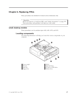
Lenovo NetVista A22p Hardware Maintenance Manual (HMM) for NetVista 2292, 6343 - Page 35
Replacing, microprocessor
 |
View all Lenovo NetVista A22p manuals
Add to My Manuals
Save this manual to your list of manuals |
Page 35 highlights
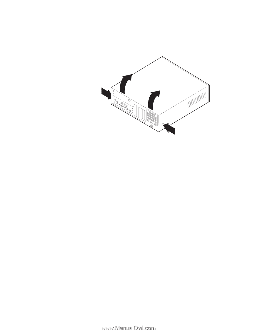
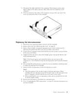
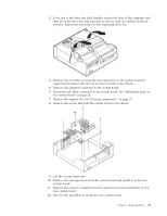
3. Disconnect all cables attached to the computer. This includes power cords, input/output (I/O) cables, and any other cables that are connected to the computer. 4. Press the buttons on the sides of the computer and pivot the rear end of the cover up toward the front of the computer. Replacing the microprocessor 1. Shut down your operating system and turn off the computer. 2. Remove the cover. See "Removing the cover" on page 28. 3. Remove the air baffle covering the microprocessor on the system board by squeezing the plastic tabs that secure the air baffle to the chassis. 4. Loosen the two captured screws that hold the fan sink in place and pivot them off the fan sink notches. 5. Gently twist the fan sink to break the thermal grease seal and lift the fan sink off the microprocessor. Note: If the thermal grease seal cannot be broken, you can turn on the computer for a few mimutes to heat the microprocessor and loosen the thermal grease. 6. Pull out and lift up the processor socket lever to its maximum vertical position to release the microprocessor module. 7. Gently lift the microprocessor off the microprocessor socket. Notes: a. Note the position of the beveled corner on the microprocessor. When installing the new microprocessor, the beveled corner on the microprocessor must be properly oriented with the beveled corner in the socket. b. When installing the new microprocessor, make sure to reinstall the fan sink to insure proper cooling. 8. Reverse this procedure to install the new microprocessor. 9. Go to "Completing the FRU replacement." on page 45 when the microprocessor has been installed. Chapter 6. Replacing FRUs 29
-
 1
1 -
2
-
3
-
4
-
5
-
6
-
7
-
8
-
9
-
10
-
11
-
12
-
13
-
14
-
15
-
16
-
17
-
18
-
19
-
20
-
21
-
22
-
23
-
24
-
25
-
26
-
27
-
28
-
29
-
 30
30 -
 31
31 -
 32
32 -
 33
33 -
 34
34 -
 35
35 -
 36
36 -
 37
37 -
 38
38 -
 39
39 -
 40
40 -
41
-
42
-
43
-
44
-
45
-
46
-
47
-
48
-
49
-
50
-
51
-
52
-
53
-
54
-
55
-
56
-
57
-
58
-
59
-
60
-
61
-
62
-
63
-
64
-
65
-
66
-
67
-
68
-
69
-
70
-
71
-
72
-
73
-
74
-
75
-
76
-
77
-
78
-
79
-
80
-
81
-
82
-
83
-
84
-
85
-
86
-
87
-
88
-
89
-
90
-
91
-
92
-
93
-
94
-
95
-
96
-
97
-
98
-
99
-
100
-
101
-
102
-
103
-
104
-
105
-
106
-
107
-
108
-
109
-
110
-
111
-
112
-
113
-
114
-
115
-
116
-
117
-
118
-
119
-
120
-
121
-
122
-
123
-
124
-
125
-
126
-
127
-
128
-
129
-
130
-
131
-
132
-
133
-
134
-
135
-
136
-
137
-
138
-
139
-
140
-
141
-
142
-
143
-
144
-
145
-
146
-
147
-
148
-
149
-
150
-
151
-
152
-
153
-
154
-
155
-
156
-
157
-
158
-
159
-
160
-
161
-
162
-
163
-
164
-
165
-
166
-
167
-
168
-
169
-
170
-
171
-
172
-
173
-
174
-
175
-
176
-
177
-
178
-
179
-
180
-
181
-
182
-
183
-
184
-
185
-
186
-
187
-
188
-
189
-
190
-
191
-
192
-
193
-
194
-
195
-
196
-
197
-
198
-
199
-
200
-
201
-
202
-
203
-
204
-
205
-
206
-
207
-
208
-
209
-
210
-
211
-
212
-
213
-
214
-
215
-
216
-
217
-
218
-
219
-
220
-
221
-
222
-
223
-
224
-
225
-
226
-
227
-
228
-
229
-
230
 |
 |