Lenovo NetVista A40 Hardware Maintenance Manual (HMM) for NetVista 2271, 6840, - Page 36
Clear CMOS/Flash Boot Block Recovery, Processor Speed Settings, System board memory, Installing memory
 |
View all Lenovo NetVista A40 manuals
Add to My Manuals
Save this manual to your list of manuals |
Page 36 highlights
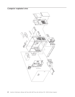
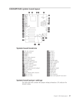
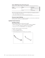
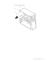
Clear CMOS/Flash Boot Block Recovery Use the recovery jumper setting to Clear CMOS or to Flash Boot Block Recover. Jumper CMOS Reset Setting 2-3 1-2 (D) Description CMOS Reset/Flash Recovery Mode Normal Mode Note: The A40/A40P/A40i CMOS clear/recovery jumper pins are numbered as follows: v Pin 1 is the farthest from the battery. v Pins 2 and 3 are below pin 1, as seen in the System Board layout. Processor Speed Settings Processor speed for type 2271/6840/6841 computers are fixed and are determined by the processor. There are no settings required. System board memory Installing memory When installing DIMMs, the following rules apply: v Fill each system memory connector sequentially, starting at DIMM 0. v Use 3.3 V, 133 MHz, unbuffered, SDRAM non-parity DIMMs. v Use only 64, 128, or 256 MB DIMMs in any combination. To install a memory module, do the following: 1. Remove the AGP adapter. 2. Locate the DIMM connectors. 3. If the retaining clips are not already open, open them. 30 Hardware Maintenance Manual A40 Type 6840 A40P Type 6841 A40i Type 2271: IBM NetVista Computer
-
 1
1 -
2
-
3
-
4
-
5
-
6
-
7
-
8
-
9
-
10
-
11
-
12
-
13
-
14
-
15
-
16
-
17
-
18
-
19
-
20
-
21
-
22
-
23
-
24
-
25
-
26
-
27
-
28
-
29
-
30
-
 31
31 -
 32
32 -
 33
33 -
 34
34 -
 35
35 -
 36
36 -
 37
37 -
 38
38 -
 39
39 -
 40
40 -
 41
41 -
42
-
43
-
44
-
45
-
46
-
47
-
48
-
49
-
50
-
51
-
52
-
53
-
54
-
55
-
56
-
57
-
58
-
59
-
60
-
61
-
62
-
63
-
64
-
65
-
66
-
67
-
68
-
69
-
70
-
71
-
72
-
73
-
74
-
75
-
76
-
77
-
78
-
79
-
80
-
81
-
82
-
83
-
84
-
85
-
86
-
87
-
88
-
89
-
90
-
91
-
92
-
93
-
94
-
95
-
96
-
97
-
98
-
99
-
100
-
101
-
102
-
103
-
104
-
105
-
106
-
107
-
108
-
109
-
110
-
111
-
112
-
113
-
114
-
115
-
116
-
117
-
118
-
119
-
120
-
121
-
122
-
123
-
124
-
125
-
126
-
127
-
128
-
129
-
130
-
131
-
132
-
133
-
134
-
135
-
136
-
137
-
138
-
139
-
140
-
141
-
142
-
143
-
144
-
145
-
146
-
147
-
148
 |
 |