Lenovo S210 Laptop Hardware Maintenance Manual - IdeaPad S210, S210 Touch, S21 - Page 57
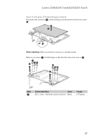
Remove screws, M2 × 2.5 mm, flat-head, nylok
 |
View all Lenovo S210 Laptop manuals
Add to My Manuals
Save this manual to your list of manuals |
Page 57 highlights
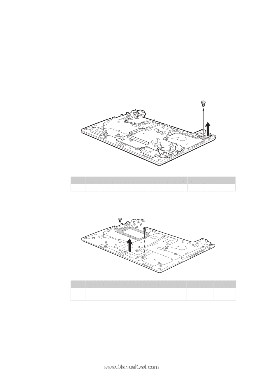
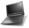
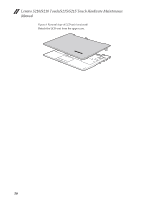
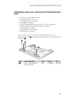
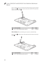
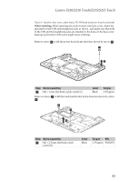
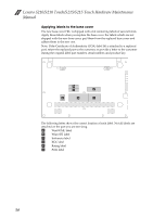
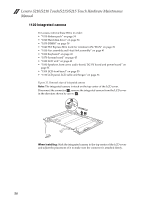
Lenovo S210/S210 Touch/S215/S215 Touch Figure 9. Speakers, base cover, audio board, DC-IN board and power board (continued) When installing: When attaching the audio board to the base cover, adjust the placement of the USB and headphone jacks as shown , and make sure that both of the USB and the headphone jacks are attached to the holes on the base cover. Improper placement of the jacks might cause a damage. Remove screw a to lift the power board in the direction shown by arrow b . a b Step Screw (quantity) a M2 × 3 mm, flat-head, nylok-coated (1) Color Black Torque 1.35 kgfcm Remove screws a to lift the touch pad bracket in the direction shown by arrow b. a a b Step Screw (quantity) a M2 × 2.5 mm, flat-head, nylok- coated (2) Color Black Torque P/N 1.35 kgfcm 90202951 53
-
 1
1 -
2
-
3
-
4
-
5
-
6
-
7
-
8
-
9
-
10
-
11
-
12
-
13
-
14
-
15
-
16
-
17
-
18
-
19
-
20
-
21
-
22
-
23
-
24
-
25
-
26
-
27
-
28
-
29
-
30
-
31
-
32
-
33
-
34
-
35
-
36
-
37
-
38
-
39
-
40
-
41
-
42
-
43
-
44
-
45
-
46
-
47
-
48
-
49
-
50
-
51
-
 52
52 -
 53
53 -
 54
54 -
 55
55 -
 56
56 -
 57
57 -
 58
58 -
 59
59 -
 60
60 -
 61
61 -
 62
62 -
63
-
64
-
65
-
66
-
67
-
68
-
69
-
70
-
71
-
72
-
73
-
74
-
75
-
76
-
77
-
78
-
79
-
80
-
81
-
82
-
83
-
84
-
85
-
86
-
87
-
88
-
89
-
90
 |
 |