Lenovo S41-70 Laptop Hardware Maintenance Manual - Lenovo S41-70, U41-70 - Page 55
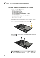
Removal steps of power assembly, touchpad module and IO board, Remove screw
 |
View all Lenovo S41-70 Laptop manuals
Add to My Manuals
Save this manual to your list of manuals |
Page 55 highlights
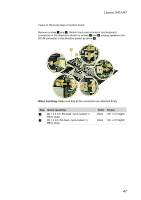
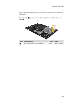
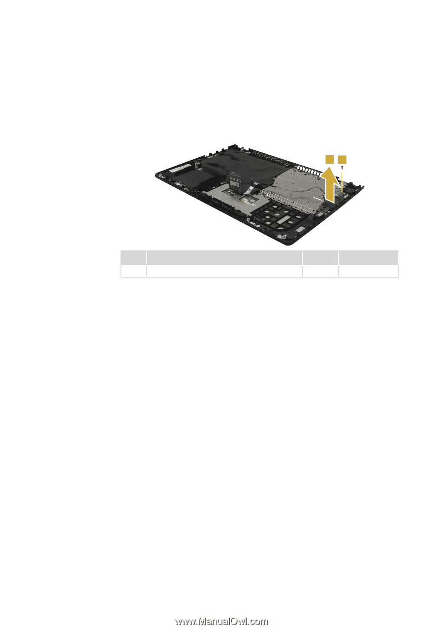
Lenovo S41/U41 Figure 10. Removal steps of power assembly, touchpad module and IO board (continued) Remove screw 1, and then remove the IO board in the direction shown by arrow 2. 21 Step Screw (quantity) 1 M2 × 4 mm, flat-head, nylok-coated (1) Color Torque Silver 1.85+/-0.15 kgfcm 51
-
 1
1 -
2
-
3
-
4
-
5
-
6
-
7
-
8
-
9
-
10
-
11
-
12
-
13
-
14
-
15
-
16
-
17
-
18
-
19
-
20
-
21
-
22
-
23
-
24
-
25
-
26
-
27
-
28
-
29
-
30
-
31
-
32
-
33
-
34
-
35
-
36
-
37
-
38
-
39
-
40
-
41
-
42
-
43
-
44
-
45
-
46
-
47
-
48
-
49
-
 50
50 -
 51
51 -
 52
52 -
 53
53 -
 54
54 -
 55
55 -
 56
56 -
 57
57 -
 58
58 -
 59
59 -
 60
60 -
61
-
62
-
63
-
64
-
65
-
66
-
67
-
68
-
69
-
70
-
71
-
72
-
73
-
74
-
75
-
76
-
77
-
78
-
79
-
80
-
81
-
82
 |
 |
51
Lenovo S41/U41
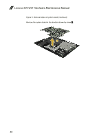
Figure 10. Removal steps of power assembly, touchpad module and IO board
(continued)
Remove screw
1
, and then remove the IO board in the direction shown by
arrow
2
.
2
1
Step
Screw (quantity)
Color
Torque
1
M2 × 4 mm, flat-head, nylok-coated (1)
Silver
1.85+/-0.15 kgfcm