Lenovo S500 Touch Laptop Hardware Maintenance Manual - IdeaPad S500, S500 Touc - Page 51
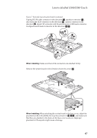
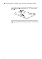
When attaching the system board to the base cover, adjust
 |
View all Lenovo S500 Touch Laptop manuals
Add to My Manuals
Save this manual to your list of manuals |
Page 51 highlights
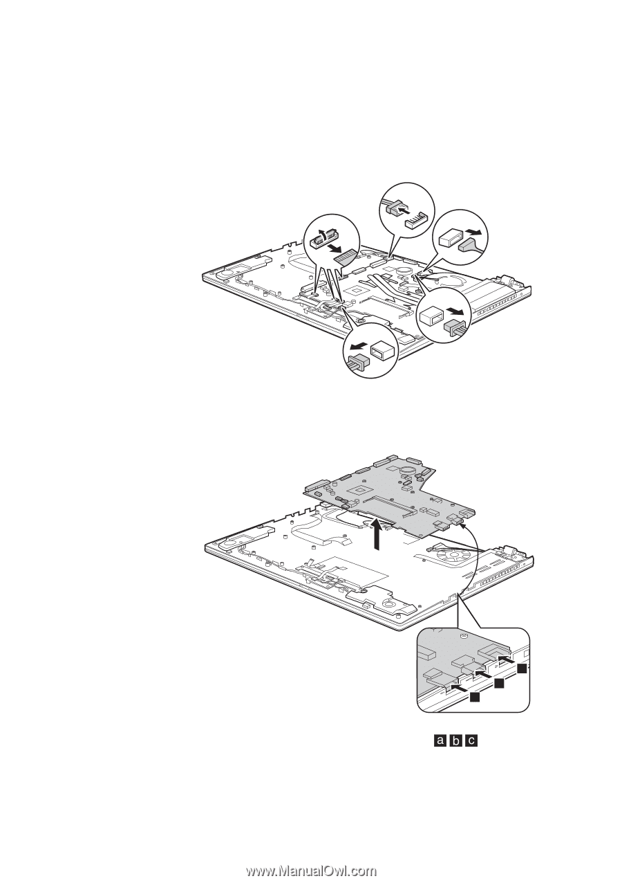
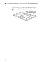
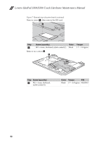
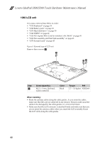
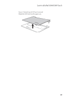
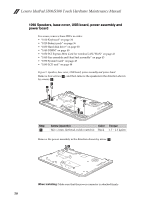
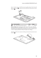
Lenovo IdeaPad S500/S500 Touch Figure 7. Removal steps of system board (continued) Unplug DC-IN cable connector in the direction c , speakers connector d , disconnect the LCD connector in the direction e , camera connector in the direction h , detach TP connector, LED board connector, USB board connector, touchpad board bracket connector in the direction f g . c f e g h d When installing: Make sure that all the connectors are attached firmly. Remove the system board in the direction shown by arrow i. i c b a When installing: When attaching the system board to the base cover, adjust the placement of the USB, HDMI, RJ-45 ports as shown in , and make sure that they are attached to the holes on the base cover as shown. Improper placement of those jacks might cause a damage. 47
-
 1
1 -
2
-
3
-
4
-
5
-
6
-
7
-
8
-
9
-
10
-
11
-
12
-
13
-
14
-
15
-
16
-
17
-
18
-
19
-
20
-
21
-
22
-
23
-
24
-
25
-
26
-
27
-
28
-
29
-
30
-
31
-
32
-
33
-
34
-
35
-
36
-
37
-
38
-
39
-
40
-
41
-
42
-
43
-
44
-
45
-
 46
46 -
 47
47 -
 48
48 -
 49
49 -
 50
50 -
 51
51 -
 52
52 -
 53
53 -
 54
54 -
 55
55 -
 56
56 -
57
-
58
-
59
-
60
-
61
-
62
-
63
-
64
-
65
-
66
-
67
-
68
-
69
-
70
-
71
-
72
-
73
-
74
-
75
-
76
-
77
-
78
-
79
-
80
-
81
-
82
-
83
-
84
 |
 |