Lenovo ThinkCentre Edge 62 Hardware Maintenance Manual - Page 129
Reinstall the foot stands. See Removing and reinstalling the foot stands
 |
View all Lenovo ThinkCentre Edge 62 manuals
Add to My Manuals
Save this manual to your list of manuals |
Page 129 highlights
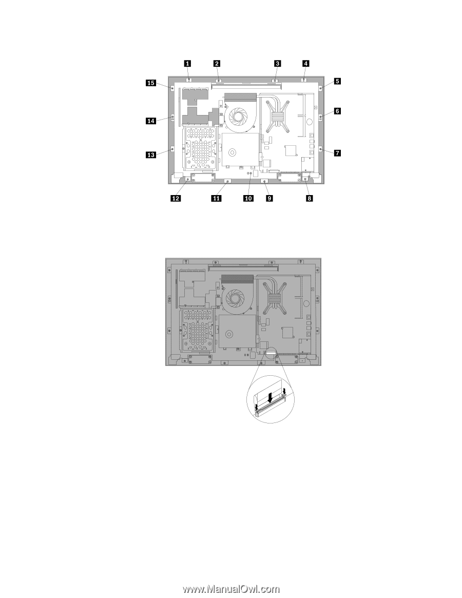
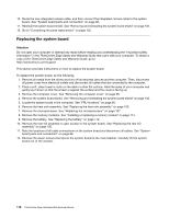
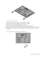
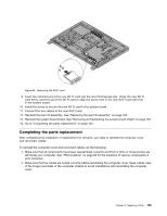
Figure 46. Reinstalling all the 15 screws that secure the computer main bracket to the front bezel 19. Reconnect the LCD panel cable to the system board. See Figure 47. Reconnect the LCD panel cable to the system board 20. Reinstall the integrated camera. See "Replacing the integrated camera" on page 117. 21. Reinstall the rear I/O assembly. See "Replacing the rear I/O assembly" on page 100. 22. Reinstall the system board shield. See "Removing and reinstalling the system board shield" on page 102. 23. Reinstall the foot stands. See "Removing and reinstalling the foot stands" on page 92. 24. Connect all the cables that were disconnected. See "System board parts and connectors" on page 88. 25. Go to "Completing the parts replacement" on page 125. Chapter 8. Replacing FRUs 123
-
 1
1 -
2
-
3
-
4
-
5
-
6
-
7
-
8
-
9
-
10
-
11
-
12
-
13
-
14
-
15
-
16
-
17
-
18
-
19
-
20
-
21
-
22
-
23
-
24
-
25
-
26
-
27
-
28
-
29
-
30
-
31
-
32
-
33
-
34
-
35
-
36
-
37
-
38
-
39
-
40
-
41
-
42
-
43
-
44
-
45
-
46
-
47
-
48
-
49
-
50
-
51
-
52
-
53
-
54
-
55
-
56
-
57
-
58
-
59
-
60
-
61
-
62
-
63
-
64
-
65
-
66
-
67
-
68
-
69
-
70
-
71
-
72
-
73
-
74
-
75
-
76
-
77
-
78
-
79
-
80
-
81
-
82
-
83
-
84
-
85
-
86
-
87
-
88
-
89
-
90
-
91
-
92
-
93
-
94
-
95
-
96
-
97
-
98
-
99
-
100
-
101
-
102
-
103
-
104
-
105
-
106
-
107
-
108
-
109
-
110
-
111
-
112
-
113
-
114
-
115
-
116
-
117
-
118
-
119
-
120
-
121
-
122
-
123
-
 124
124 -
 125
125 -
 126
126 -
 127
127 -
 128
128 -
 129
129 -
 130
130 -
 131
131 -
 132
132 -
 133
133 -
 134
134 -
135
-
136
-
137
-
138
-
139
-
140
-
141
-
142
-
143
-
144
-
145
-
146
-
147
-
148
-
149
-
150
-
151
-
152
-
153
-
154
-
155
-
156
-
157
-
158
-
159
-
160
-
161
-
162
-
163
-
164
-
165
-
166
-
167
-
168
-
169
-
170
-
171
-
172
-
173
-
174
-
175
-
176
-
177
-
178
-
179
-
180
-
181
-
182
 |
 |