Lenovo ThinkCentre M90 Hardware Maintenance Manual - Page 88
Replacing the hard disk drive
 |
View all Lenovo ThinkCentre M90 manuals
Add to My Manuals
Save this manual to your list of manuals |
Page 88 highlights
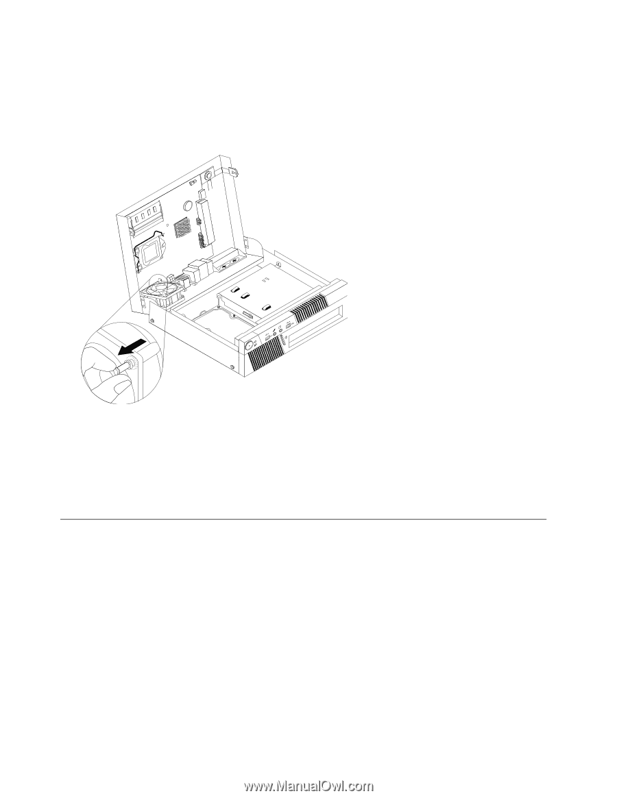
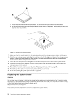
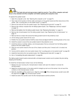
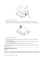
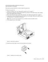
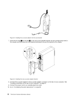
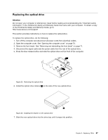
7. Install the two long rubber mounts into the rear of the chassis. Push the mounts through the holes of the chassis. If necessary, pull the mounts through the holes from inside the chassis. 8. To install the new system fan assembly into the chassis, align the open holes in the system fan assembly with the long rubber mounts in the chassis. Pull the rubber mounts through the holes in the system fan assembly until the fan is in place. Figure 18. Replacing the system fan assembly 9. Once the system fan assembly is secure, you should remove the extra rubber from the mounts. 10. Connect the system fan assembly cable to the fan connector on the system board. 11. Replace the heat sink. See "Replacing the heat sink" on page 75. 12. Go to "Completing the parts replacement" on page 89. Replacing the hard disk drive Attention Do not open your computer or attempt any repair before reading and understanding the "Important safety information" in the ThinkCentre Safety and Warranty Guide that came with your computer. To obtain a copy of the ThinkCentre Safety and Warranty Guide, go to: http://www.lenovo.com/support This section provides instructions on how to replace the hard disk drive if your computer has one. For computer models that do not have an internal hard disk drive installed and use a remote hard disk drive accessed through the SMC - Storage Array, contact your network or storage administrator. To replace the hard disk drive, do the following: 1. Turn off the computer and disconnect all power cords from electrical outlets. 2. Open the computer cover. See "Opening the computer cover" on page 70. 82 ThinkCentre Hardware Maintenance Manual
-
 1
1 -
2
-
3
-
4
-
5
-
6
-
7
-
8
-
9
-
10
-
11
-
12
-
13
-
14
-
15
-
16
-
17
-
18
-
19
-
20
-
21
-
22
-
23
-
24
-
25
-
26
-
27
-
28
-
29
-
30
-
31
-
32
-
33
-
34
-
35
-
36
-
37
-
38
-
39
-
40
-
41
-
42
-
43
-
44
-
45
-
46
-
47
-
48
-
49
-
50
-
51
-
52
-
53
-
54
-
55
-
56
-
57
-
58
-
59
-
60
-
61
-
62
-
63
-
64
-
65
-
66
-
67
-
68
-
69
-
70
-
71
-
72
-
73
-
74
-
75
-
76
-
77
-
78
-
79
-
80
-
81
-
82
-
 83
83 -
 84
84 -
 85
85 -
 86
86 -
 87
87 -
 88
88 -
 89
89 -
 90
90 -
 91
91 -
 92
92 -
 93
93 -
94
-
95
-
96
-
97
-
98
-
99
-
100
-
101
-
102
-
103
-
104
-
105
-
106
-
107
-
108
-
109
-
110
-
111
-
112
-
113
-
114
-
115
-
116
-
117
-
118
-
119
-
120
-
121
-
122
-
123
-
124
-
125
-
126
-
127
-
128
-
129
-
130
-
131
-
132
-
133
-
134
-
135
-
136
-
137
-
138
-
139
-
140
-
141
-
142
-
143
-
144
-
145
-
146
-
147
-
148
-
149
-
150
-
151
-
152
-
153
-
154
-
155
-
156
-
157
-
158
-
159
-
160
-
161
-
162
-
163
-
164
-
165
-
166
-
167
-
168
-
169
-
170
-
171
-
172
-
173
-
174
-
175
-
176
-
177
-
178
-
179
-
180
-
181
-
182
-
183
-
184
-
185
-
186
-
187
-
188
-
189
-
190
-
191
-
192
-
193
-
194
-
195
-
196
-
197
-
198
-
199
-
200
-
201
-
202
-
203
-
204
-
205
-
206
-
207
-
208
-
209
-
210
-
211
-
212
-
213
-
214
-
215
-
216
-
217
-
218
-
219
-
220
-
221
-
222
-
223
-
224
 |
 |