Lenovo ThinkPad 600 Technical Reference Manual for the ThinkPad 600 - Page 69
V dc is .5 A for each slot including, When the computer is in suspend mode,
 |
View all Lenovo ThinkPad 600 manuals
Add to My Manuals
Save this manual to your list of manuals |
Page 69 highlights
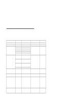
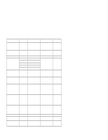
Pin 16-Bit PC Card 31 D1 32 D2 33 IOIS16# 34 Ground 35 Ground 36 CD1# 37 D11 38 D12 39 D13 40 D14 41 D15 42 CE2 43 VS1# 44 IORD# 45 IOWR# 46 A17 47 A18 48 A19 49 A20 50 A21 51 Vcc 52 Vpp 53 A22 54 A23 55 A24 56 A25 57 AS2# 58 RESET 59 WAIT# 60 INPACK# 61 REG# 62 SPKR# 63 STSCHG# 64 D8 65 D9 66 D10 67 CD2# 68 GND 32-Bit PC Card CAD29 Reserved CCLKRUN# Ground Ground CCD1# CAD2 CAD4 CAD6 Reserved CAD8 CAD10 CVS1 CAD13 CAD15 CAD16 Reserved CBLOCK# CSTOP# CDEVSEL# Vcc Vpp CTRDY# CFRAME# CAD17 CAD19 CVS2 CRST# CSERR# CREQ# CC/BE3# CAUDIO CSTSCHG CAD28 CAD30 CAD31 CCD2# GND Figure 3-3 (Part 2 of 2). PCMCIA PC Card Slot Pin Assignments The maximum current for +5 V dc is .5 A for each slot (including both slots and V pp). The maximum current for +12 V dc is .5 A for each slot (including both slots and V pp). When the computer is in suspend mode, it requires a current of 0.05 A. Subsystems 3-11
-
 1
1 -
2
-
3
-
4
-
5
-
6
-
7
-
8
-
9
-
10
-
11
-
12
-
13
-
14
-
15
-
16
-
17
-
18
-
19
-
20
-
21
-
22
-
23
-
24
-
25
-
26
-
27
-
28
-
29
-
30
-
31
-
32
-
33
-
34
-
35
-
36
-
37
-
38
-
39
-
40
-
41
-
42
-
43
-
44
-
45
-
46
-
47
-
48
-
49
-
50
-
51
-
52
-
53
-
54
-
55
-
56
-
57
-
58
-
59
-
60
-
61
-
62
-
63
-
 64
64 -
 65
65 -
 66
66 -
 67
67 -
 68
68 -
 69
69 -
 70
70 -
 71
71 -
 72
72 -
 73
73 -
 74
74 -
75
-
76
-
77
-
78
-
79
-
80
-
81
-
82
-
83
-
84
-
85
-
86
-
87
-
88
-
89
-
90
-
91
-
92
-
93
-
94
-
95
-
96
-
97
-
98
-
99
-
100
-
101
-
102
-
103
-
104
-
105
-
106
-
107
-
108
-
109
-
110
-
111
-
112
-
113
-
114
-
115
-
116
-
117
-
118
-
119
-
120
-
121
-
122
-
123
-
124
-
125
-
126
-
127
-
128
-
129
-
130
-
131
-
132
-
133
-
134
-
135
-
136
-
137
-
138
-
139
-
140
-
141
-
142
-
143
-
144
-
145
-
146
-
147
 |
 |