Lenovo ThinkPad L430 Hardware Maintenance Manual - Page 76
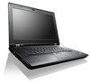
Removal steps of keyboard, When installing, and then detach the keyboard connectors
 |
View all Lenovo ThinkPad L430 manuals
Add to My Manuals
Save this manual to your list of manuals |
Page 76 highlights
Removal steps of keyboard 1 1 When installing: Ensure that the screws are fastened and the keyboard is secured. Step 1 Screw (quantity) M2 × 14 mm, flat-head, nylon-coated (2) Color Black Torque 0.181 Nm (1.85 kgfcm) Press the keyboard as shown in the following illustration until the hooks on the rear edge of the keyboard are detached from the keyboard bezel. 2 2 Lift the keyboard up 3 , and then detach the keyboard connectors 4 . 70 Hardware Maintenance Manual
-
 1
1 -
2
-
3
-
4
-
5
-
6
-
7
-
8
-
9
-
10
-
11
-
12
-
13
-
14
-
15
-
16
-
17
-
18
-
19
-
20
-
21
-
22
-
23
-
24
-
25
-
26
-
27
-
28
-
29
-
30
-
31
-
32
-
33
-
34
-
35
-
36
-
37
-
38
-
39
-
40
-
41
-
42
-
43
-
44
-
45
-
46
-
47
-
48
-
49
-
50
-
51
-
52
-
53
-
54
-
55
-
56
-
57
-
58
-
59
-
60
-
61
-
62
-
63
-
64
-
65
-
66
-
67
-
68
-
69
-
70
-
 71
71 -
 72
72 -
 73
73 -
 74
74 -
 75
75 -
 76
76 -
 77
77 -
 78
78 -
 79
79 -
 80
80 -
 81
81 -
82
-
83
-
84
-
85
-
86
-
87
-
88
-
89
-
90
-
91
-
92
-
93
-
94
-
95
-
96
-
97
-
98
-
99
-
100
-
101
-
102
-
103
-
104
-
105
-
106
-
107
-
108
-
109
-
110
-
111
-
112
-
113
-
114
-
115
-
116
-
117
-
118
-
119
-
120
 |
 |

Removal steps of keyboard
1
1
When installing:
Ensure that the screws are fastened and the keyboard is secured.
Step
Screw (quantity)
Color
Torque
1
M2 × 14 mm, flat-head, nylon-coated (2)
Black
0.181 Nm
(1.85 kgfcm)
Press the keyboard as shown in the following illustration until the hooks on the rear edge of the keyboard
are detached from the keyboard bezel.
2
2
Lift the keyboard up
3
, and then detach the keyboard connectors
4
.
70
Hardware Maintenance Manual