Lenovo ThinkPad SL410 Hardware Maintenance Manual - Page 112
Integrated camera - hinges
 |
View all Lenovo ThinkPad SL410 manuals
Add to My Manuals
Save this manual to your list of manuals |
Page 112 highlights
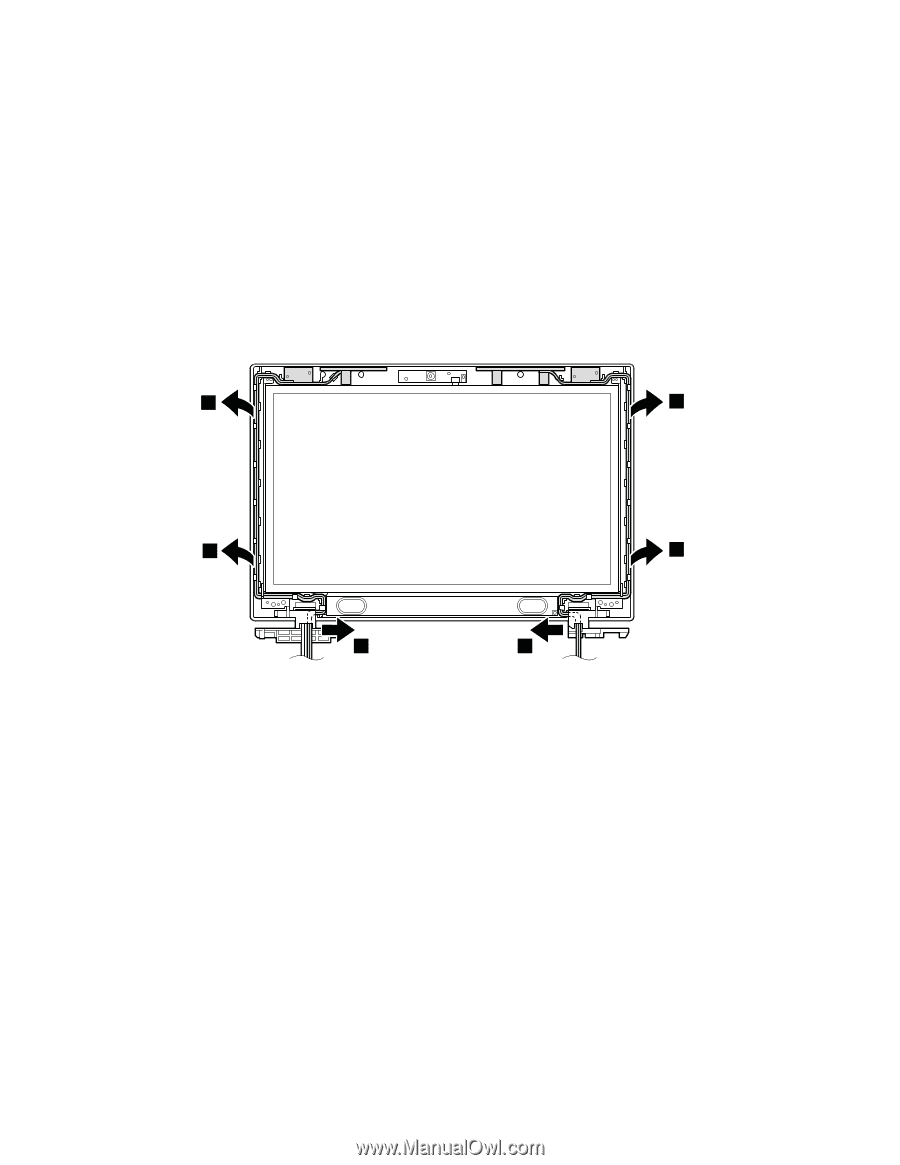
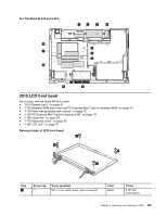
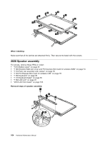
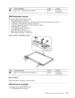
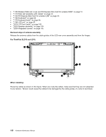
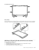
• "1100 Wireless WAN slot cover and PCI Express Mini Card for wireless WAN" on page 74 • "1110 Palm rest assembly with cables" on page 76 • "1120 PCI Express Mini Card for wireless LAN" on page 78 • "1160 Keyboard" on page 83 • "1170 Keyboard bezel" on page 85 • "1180 LCD unit" on page 87 • "2010 LCD front bezel" on page 103 • "2020 Speaker assembly" on page 104 • "2030 Integrated camera" on page 105 Removal steps of antenna assembly Release the antenna cables from the cable guides of the LCD rear cover assembly and from the hinges. For ThinkPad SL510 and L510: 1 1 1 1 1 1 When installing: Route the cables as shown in this figure. When you route the cables, make sure that they are not subjected to any tension. Tension could cause the cables to be damaged by the cable guides, or a wire to be broken. 106 Hardware Maintenance Manual
-
 1
1 -
2
-
3
-
4
-
5
-
6
-
7
-
8
-
9
-
10
-
11
-
12
-
13
-
14
-
15
-
16
-
17
-
18
-
19
-
20
-
21
-
22
-
23
-
24
-
25
-
26
-
27
-
28
-
29
-
30
-
31
-
32
-
33
-
34
-
35
-
36
-
37
-
38
-
39
-
40
-
41
-
42
-
43
-
44
-
45
-
46
-
47
-
48
-
49
-
50
-
51
-
52
-
53
-
54
-
55
-
56
-
57
-
58
-
59
-
60
-
61
-
62
-
63
-
64
-
65
-
66
-
67
-
68
-
69
-
70
-
71
-
72
-
73
-
74
-
75
-
76
-
77
-
78
-
79
-
80
-
81
-
82
-
83
-
84
-
85
-
86
-
87
-
88
-
89
-
90
-
91
-
92
-
93
-
94
-
95
-
96
-
97
-
98
-
99
-
100
-
101
-
102
-
103
-
104
-
105
-
106
-
 107
107 -
 108
108 -
 109
109 -
 110
110 -
 111
111 -
 112
112 -
 113
113 -
 114
114 -
 115
115 -
 116
116 -
 117
117 -
118
-
119
-
120
-
121
-
122
-
123
-
124
-
125
-
126
-
127
-
128
-
129
-
130
-
131
-
132
-
133
-
134
-
135
-
136
-
137
-
138
-
139
-
140
-
141
-
142
-
143
-
144
-
145
-
146
-
147
-
148
-
149
-
150
-
151
-
152
-
153
-
154
-
155
-
156
-
157
-
158
-
159
-
160
-
161
-
162
-
163
-
164
-
165
-
166
-
167
-
168
-
169
-
170
-
171
-
172
-
173
-
174
-
175
-
176
-
177
 |
 |