Lenovo ThinkPad T410i Hardware Maintenance Manual - Page 97
LCD unit, 1110 PCI Express Mini Card for wireless LAN
 |
View all Lenovo ThinkPad T410i manuals
Add to My Manuals
Save this manual to your list of manuals |
Page 97 highlights
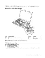
When installing: Attach the speaker assembly and route the cable as shown in the following figure, and make sure that the speaker connector is attached firmly. 1160 LCD unit For access, remove these FRUs in order: • "1010 Battery pack" on page 66 • "1020 ExpressCard blank bezel" on page 67 • "1050 DIMM slot cover" on page 70 • "1070 PCI Express Mini Card for wireless WAN" on page 72 • "1080 Keyboard" on page 74 • "1110 PCI Express Mini Card for wireless LAN" on page 81 • "1120 Keyboard bezel assembly, FPC cable, and Bluethooth daughter card (BDC-2.1)" on page 83 Removal steps of LCD unit 1 1 Step 1 Screw (quantity) M2.5 × 6 mm, wafer-head, nylon-coated (2) Color Black Torque 0.392 Nm (4.0 kgfcm) Chapter 8. Removing and replacing a FRU 91
-
 1
1 -
2
-
3
-
4
-
5
-
6
-
7
-
8
-
9
-
10
-
11
-
12
-
13
-
14
-
15
-
16
-
17
-
18
-
19
-
20
-
21
-
22
-
23
-
24
-
25
-
26
-
27
-
28
-
29
-
30
-
31
-
32
-
33
-
34
-
35
-
36
-
37
-
38
-
39
-
40
-
41
-
42
-
43
-
44
-
45
-
46
-
47
-
48
-
49
-
50
-
51
-
52
-
53
-
54
-
55
-
56
-
57
-
58
-
59
-
60
-
61
-
62
-
63
-
64
-
65
-
66
-
67
-
68
-
69
-
70
-
71
-
72
-
73
-
74
-
75
-
76
-
77
-
78
-
79
-
80
-
81
-
82
-
83
-
84
-
85
-
86
-
87
-
88
-
89
-
90
-
91
-
 92
92 -
 93
93 -
 94
94 -
 95
95 -
 96
96 -
 97
97 -
 98
98 -
 99
99 -
 100
100 -
 101
101 -
 102
102 -
103
-
104
-
105
-
106
-
107
-
108
-
109
-
110
-
111
-
112
-
113
-
114
-
115
-
116
-
117
-
118
-
119
-
120
-
121
-
122
-
123
-
124
-
125
-
126
-
127
-
128
-
129
-
130
-
131
-
132
-
133
-
134
-
135
-
136
-
137
-
138
-
139
-
140
-
141
-
142
-
143
-
144
-
145
-
146
-
147
-
148
-
149
-
150
-
151
-
152
-
153
-
154
-
155
-
156
-
157
-
158
-
159
-
160
-
161
-
162
-
163
-
164
-
165
-
166
-
167
-
168
-
169
-
170
-
171
-
172
-
173
-
174
 |
 |
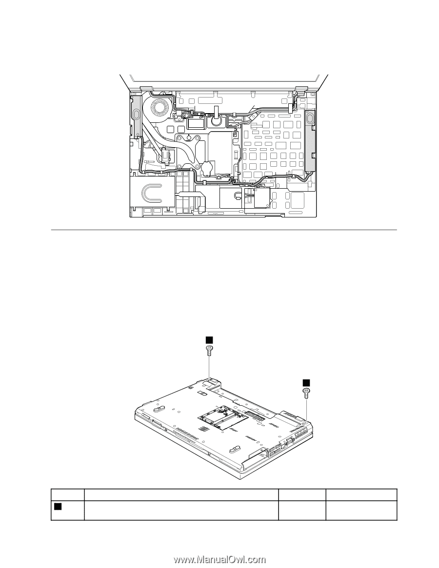
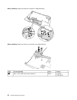
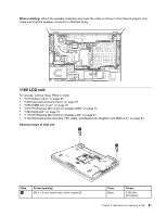
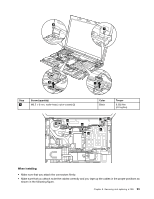
When installing:
Attach the speaker assembly and route the cable as shown in the following figure, and
make sure that the speaker connector is attached firmly.
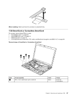
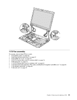
1160 LCD unit
For access, remove these FRUs in order:
•
“1010 Battery pack” on page 66
•
“1020 ExpressCard blank bezel” on page 67
•
“1050 DIMM slot cover” on page 70
•
“1070 PCI Express Mini Card for wireless WAN” on page 72
•
“1080 Keyboard” on page 74
•
“1110 PCI Express Mini Card for wireless LAN” on page 81
•
“1120 Keyboard bezel assembly, FPC cable, and
Bluethooth
daughter card (BDC-2.1)” on page 83
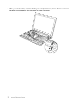
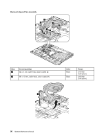
Removal steps of LCD unit
1
1
Step
Screw (quantity)
Color
Torque
1
M2.5 × 6 mm, wafer-head, nylon-coated (2)
Black
0.392 Nm
(4.0 kgfcm)
Chapter 8
.
Removing and replacing a FRU
91