Lenovo ThinkPad T410si Hardware Maintenance Manual - Page 96
indicate the removal steps of fan assembly, and those from, The steps
 |
View all Lenovo ThinkPad T410si manuals
Add to My Manuals
Save this manual to your list of manuals |
Page 96 highlights
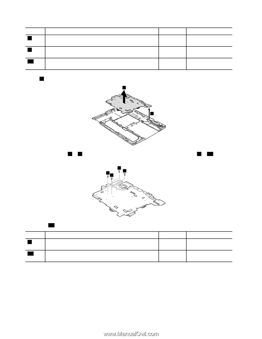
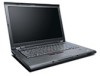
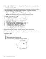
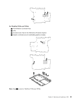
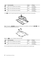
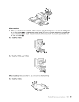
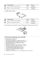
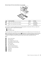
Step 1 2 2a Screw (quantity) M2 × 3.5 mm, big-head, nylon-coated (3) M2 × 6 mm, bind-head, nylon-coated (1) M2 × 6 mm, bind-head, nylon-coated (2) Color Black Black Black Torque 0.181 Nm (1.85 kgfcm) 0.181 Nm (1.85 kgfcm) 0.181 Nm (1.85 kgfcm) In step 4 , remove the system board and fan assembly together from the base cover assembly. 4 3 Note: The steps from 5 to 7 indicate the removal steps of fan assembly, and those from 8 to 11 indicate the ones of 34-mm ExpressCard slot frame. 5a 5 5 5 Note: Step 5a is only for ThinkPad T410s and T410si. Step 5 Screw (quantity) M2 × 3.5 mm, big-head, nylon-coated (3) 5a M2 × 3.5 mm, big-head, nylon-coated (1) Color Black Black Torque 0.181 Nm (1.85 kgfcm) 0.181 Nm (1.85 kgfcm) Turn the system board over, and then disconnect the fan assembly from the system board. 90 Hardware Maintenance Manual
-
 1
1 -
2
-
3
-
4
-
5
-
6
-
7
-
8
-
9
-
10
-
11
-
12
-
13
-
14
-
15
-
16
-
17
-
18
-
19
-
20
-
21
-
22
-
23
-
24
-
25
-
26
-
27
-
28
-
29
-
30
-
31
-
32
-
33
-
34
-
35
-
36
-
37
-
38
-
39
-
40
-
41
-
42
-
43
-
44
-
45
-
46
-
47
-
48
-
49
-
50
-
51
-
52
-
53
-
54
-
55
-
56
-
57
-
58
-
59
-
60
-
61
-
62
-
63
-
64
-
65
-
66
-
67
-
68
-
69
-
70
-
71
-
72
-
73
-
74
-
75
-
76
-
77
-
78
-
79
-
80
-
81
-
82
-
83
-
84
-
85
-
86
-
87
-
88
-
89
-
90
-
 91
91 -
 92
92 -
 93
93 -
 94
94 -
 95
95 -
 96
96 -
 97
97 -
 98
98 -
 99
99 -
 100
100 -
 101
101 -
102
-
103
-
104
-
105
-
106
-
107
-
108
-
109
-
110
-
111
-
112
-
113
-
114
-
115
-
116
-
117
-
118
-
119
-
120
-
121
-
122
-
123
-
124
-
125
-
126
-
127
-
128
-
129
-
130
-
131
-
132
-
133
-
134
-
135
-
136
-
137
-
138
-
139
-
140
-
141
-
142
-
143
-
144
-
145
-
146
-
147
-
148
-
149
-
150
-
151
-
152
-
153
-
154
-
155
-
156
-
157
-
158
-
159
-
160
-
161
-
162
-
163
-
164
-
165
-
166
 |
 |