Lenovo ThinkPad T420i Hardware Maintenance Manual - Page 127
LCD panel and LCD cable
 |
View all Lenovo ThinkPad T420i manuals
Add to My Manuals
Save this manual to your list of manuals |
Page 127 highlights
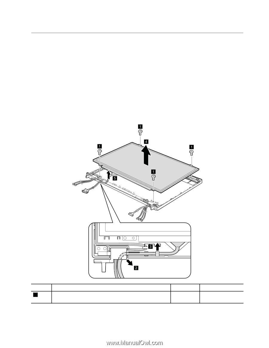
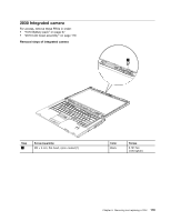
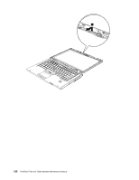
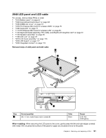
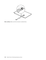
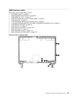
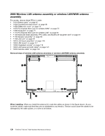
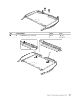
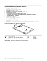
2040 LCD panel and LCD cable For access, remove these FRUs in order: • "1010 Battery pack" on page 67 • "1020 ExpressCard blank bezel" on page 68 • "1050 DIMM slot cover" on page 73 • "1070 PCI Express Mini Card for wireless WAN" on page 75 • "1080 Keyboard" on page 77 • "1110 PCI Express Mini Card for wireless LAN" on page 85 • "1120 Keyboard bezel assembly, FPC cable, and Bluethooth daughter card" on page 87 • "1150 Speaker assembly" on page 95 • "1160 LCD unit" on page 97 • "2010 LCD bezel assembly" on page 116 • "2020 LED board" on page 117 • "2030 Integrated camera" on page 119 Removal steps of LCD panel and LCD cable 1 4 1 1 1 5 3 2 Step 1 Screw (quantity) M2 × 3 mm, wafer-head, nylon-coated (4) Color Black Torque 0.181 Nm (1.85 kgfcm) When installing: When attaching the LCD panel to the cover, gently press the left and right edges covered with metal. DO not press the surface of the panel or apply any excessive force to the panel. Chapter 8. Removing and replacing a FRU 121
-
 1
1 -
2
-
3
-
4
-
5
-
6
-
7
-
8
-
9
-
10
-
11
-
12
-
13
-
14
-
15
-
16
-
17
-
18
-
19
-
20
-
21
-
22
-
23
-
24
-
25
-
26
-
27
-
28
-
29
-
30
-
31
-
32
-
33
-
34
-
35
-
36
-
37
-
38
-
39
-
40
-
41
-
42
-
43
-
44
-
45
-
46
-
47
-
48
-
49
-
50
-
51
-
52
-
53
-
54
-
55
-
56
-
57
-
58
-
59
-
60
-
61
-
62
-
63
-
64
-
65
-
66
-
67
-
68
-
69
-
70
-
71
-
72
-
73
-
74
-
75
-
76
-
77
-
78
-
79
-
80
-
81
-
82
-
83
-
84
-
85
-
86
-
87
-
88
-
89
-
90
-
91
-
92
-
93
-
94
-
95
-
96
-
97
-
98
-
99
-
100
-
101
-
102
-
103
-
104
-
105
-
106
-
107
-
108
-
109
-
110
-
111
-
112
-
113
-
114
-
115
-
116
-
117
-
118
-
119
-
120
-
121
-
 122
122 -
 123
123 -
 124
124 -
 125
125 -
 126
126 -
 127
127 -
 128
128 -
 129
129 -
 130
130 -
 131
131 -
 132
132 -
133
-
134
-
135
-
136
-
137
-
138
-
139
-
140
-
141
-
142
-
143
-
144
-
145
-
146
-
147
-
148
-
149
-
150
-
151
-
152
-
153
-
154
-
155
-
156
-
157
-
158
-
159
-
160
-
161
-
162
-
163
-
164
-
165
-
166
-
167
-
168
-
169
-
170
-
171
-
172
-
173
-
174
-
175
-
176
-
177
-
178
-
179
-
180
-
181
-
182
-
183
-
184
-
185
-
186
 |
 |