Lenovo ThinkPad Z61e Hardware Maintenance Manual - Page 105
Card/ExpressCard
 |
View all Lenovo ThinkPad Z61e manuals
Add to My Manuals
Save this manual to your list of manuals |
Page 105 highlights
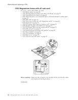
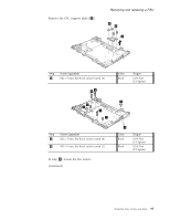
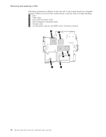
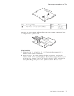
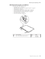
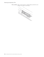
Removing and replacing a FRU 1 1 Step 1 Screw (quantity) M2 × 3 mm, flat-head, nylon-coated (2) Color Silver Torque 0.196 Nm (2.0 kgfcm) Turn over the system board, and then disconnect the PC Card/ExpressCard slots assembly from the system board. 2 When installing: 1. Make sure that the connector of PC Card/ExpressCard slots assembly is attached to the system board firmly. 2. When you attach the system board to the base cover, make sure that the wireless switch on the system board and the plastic housing in the base cover are in the same position (L or R). The wireless switch is fragile and might be damaged by the pushing force of the system board into the base cover. ThinkPad Z61e, Z61m, and Z61p 99
-
 1
1 -
2
-
3
-
4
-
5
-
6
-
7
-
8
-
9
-
10
-
11
-
12
-
13
-
14
-
15
-
16
-
17
-
18
-
19
-
20
-
21
-
22
-
23
-
24
-
25
-
26
-
27
-
28
-
29
-
30
-
31
-
32
-
33
-
34
-
35
-
36
-
37
-
38
-
39
-
40
-
41
-
42
-
43
-
44
-
45
-
46
-
47
-
48
-
49
-
50
-
51
-
52
-
53
-
54
-
55
-
56
-
57
-
58
-
59
-
60
-
61
-
62
-
63
-
64
-
65
-
66
-
67
-
68
-
69
-
70
-
71
-
72
-
73
-
74
-
75
-
76
-
77
-
78
-
79
-
80
-
81
-
82
-
83
-
84
-
85
-
86
-
87
-
88
-
89
-
90
-
91
-
92
-
93
-
94
-
95
-
96
-
97
-
98
-
99
-
 100
100 -
 101
101 -
 102
102 -
 103
103 -
 104
104 -
 105
105 -
 106
106 -
 107
107 -
 108
108 -
 109
109 -
 110
110 -
111
-
112
-
113
-
114
-
115
-
116
-
117
-
118
-
119
-
120
-
121
-
122
-
123
-
124
-
125
-
126
-
127
-
128
-
129
-
130
-
131
-
132
-
133
-
134
-
135
-
136
-
137
-
138
-
139
-
140
-
141
-
142
-
143
-
144
-
145
-
146
-
147
-
148
-
149
-
150
-
151
-
152
-
153
-
154
-
155
-
156
-
157
-
158
-
159
-
160
-
161
-
162
-
163
-
164
-
165
-
166
-
167
-
168
-
169
-
170
-
171
-
172
-
173
-
174
-
175
-
176
-
177
-
178
 |
 |
1
1
Step
Screw
(quantity)
Color
Torque
±1²
M2
×
3
mm,
flat-head,
nylon-coated
(2)
Silver
0.196
Nm
(2.0
kgfcm)
Turn
over
the
system
board,
and
then
disconnect
the
PC
Card/ExpressCard
slots
assembly
from
the
system
board.
2
When
installing:
1.
Make
sure
that
the
connector
of
PC
Card/ExpressCard
slots
assembly
is
attached
to
the
system
board
firmly.
2.
When
you
attach
the
system
board
to
the
base
cover,
make
sure
that
the
wireless
switch
on
the
system
board
and
the
plastic
housing
in
the
base
cover
are
in
the
same
position
(L
or
R).
The
wireless
switch
is
fragile
and
might
be
damaged
by
the
pushing
force
of
the
system
board
into
the
base
cover.
Removing
and
replacing
a
FRU
ThinkPad
Z61e,
Z61m,
and
Z61p
99