Lenovo ThinkPad i Series 1500 Hardware Maintenance Manual for the ThinkPad 140 - Page 81
System board, cover, gently raise the side of the system board
 |
View all Lenovo ThinkPad i Series 1500 manuals
Add to My Manuals
Save this manual to your list of manuals |
Page 81 highlights
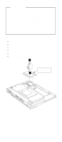
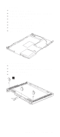
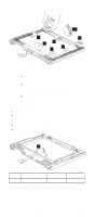
System board "Battery assembly" on page 51 "Middle cover and launch key assembly" on page 56 "Keyboard" on page 60 "Upper heat sink" on page 61 "LCD assembly" on page 65 "Keyboard bezel" on page 67 "Fan assembly" on page 70 "DC-DC charger board" on page 71 1 2 3 Step 1 Size (Quantity) M2.5 x 3.5L(3) Color Black Torque 3.2 kgf-cm 4 Notes: 1. When removing the system board from the bottom cover, gently raise the side of the system board facing the rear I/O ports; then pull out the system board. 2. When replacing the system board, align the power switch and power actuator. Make sure that the power switch operates correctly before securing the screws. 72 ThinkPad i Series 1400/1500 HMM
-
 1
1 -
2
-
3
-
4
-
5
-
6
-
7
-
8
-
9
-
10
-
11
-
12
-
13
-
14
-
15
-
16
-
17
-
18
-
19
-
20
-
21
-
22
-
23
-
24
-
25
-
26
-
27
-
28
-
29
-
30
-
31
-
32
-
33
-
34
-
35
-
36
-
37
-
38
-
39
-
40
-
41
-
42
-
43
-
44
-
45
-
46
-
47
-
48
-
49
-
50
-
51
-
52
-
53
-
54
-
55
-
56
-
57
-
58
-
59
-
60
-
61
-
62
-
63
-
64
-
65
-
66
-
67
-
68
-
69
-
70
-
71
-
72
-
73
-
74
-
75
-
 76
76 -
 77
77 -
 78
78 -
 79
79 -
 80
80 -
 81
81 -
 82
82 -
 83
83 -
 84
84 -
 85
85 -
 86
86 -
87
-
88
-
89
-
90
-
91
-
92
-
93
-
94
-
95
-
96
-
97
-
98
-
99
-
100
-
101
-
102
-
103
-
104
-
105
-
106
-
107
-
108
-
109
-
110
-
111
-
112
-
113
-
114
-
115
-
116
-
117
-
118
-
119
-
120
-
121
-
122
-
123
-
124
-
125
-
126
-
127
-
128
-
129
-
130
-
131
-
132
-
133
-
134
-
135
-
136
-
137
-
138
-
139
-
140
-
141
-
142
-
143
-
144
-
145
-
146
-
147
-
148
-
149
-
150
-
151
-
152
-
153
-
154
-
155
-
156
-
157
-
158
-
159
-
160
-
161
-
162
-
163
-
164
-
165
-
166
-
167
-
168
-
169
-
170
-
171
-
172
 |
 |

System board
±
“Battery assembly” on page
51
±
“Middle cover and launch key assembly” on page
56
±
“Keyboard” on page
60
±
“Upper heat sink” on page
61
±
“LCD assembly” on page
65
±
“Keyboard bezel” on page
67
±
“Fan assembly” on page
70
±
“DC-DC charger board” on page
71
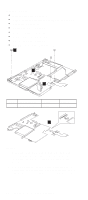
1
3
2
4
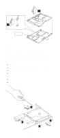
Notes:
1.
When removing the system board from the bottom
cover, gently raise the side of the system board
facing the rear I/O ports; then pull out the system
board.
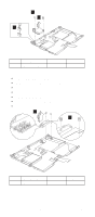
2.
When replacing the system board, align the power
switch and power actuator. Make sure that the power
switch operates correctly before securing the screws.
Step
Size (Quantity)
Color
Torque
1
M2.5 x 3.5L(3)
Black
3.2 kgf-cm
72
ThinkPad i Series 1400/1500 HMM