Lenovo U400 Laptop Hardware Maintenance Manual - IdeaPad U300, U300s and U400 - Page 80
Battery pack (U400), and one screw
 |
View all Lenovo U400 Laptop manuals
Add to My Manuals
Save this manual to your list of manuals |
Page 80 highlights
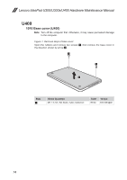
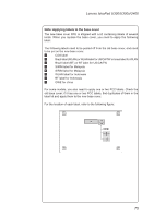
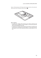
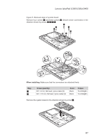
Lenovo IdeaPad U300/U300s/U400 Hardware Maintenance Manual 1020 Battery pack (U400) For access, remove this FRU: •• "1010 Base cover (U400)" on page 74 DANGER Only use the battery specified in the parts list for your computer. Any other battery could ignite or explode. Figure 2. Removal steps of battery pack Detach the battery pack connector in the direction shown by arrow 1, remove five screws 2 and one screw 3, and then remove the battery pack 4. 23 2 2 1 2 2 4 Step 2 3 Screw (quantity) M2 × 6 mm, flat-head, nylok-coated (5) M2 × 7 mm, flat-head, nylok-coated (1) Color Black White Torque 1.6 ± 0.24 kgfcm 1.6 ± 0.24 kgfcm When installing: Make sure the battery pack connector is attached firmly. 76
-
 1
1 -
2
-
3
-
4
-
5
-
6
-
7
-
8
-
9
-
10
-
11
-
12
-
13
-
14
-
15
-
16
-
17
-
18
-
19
-
20
-
21
-
22
-
23
-
24
-
25
-
26
-
27
-
28
-
29
-
30
-
31
-
32
-
33
-
34
-
35
-
36
-
37
-
38
-
39
-
40
-
41
-
42
-
43
-
44
-
45
-
46
-
47
-
48
-
49
-
50
-
51
-
52
-
53
-
54
-
55
-
56
-
57
-
58
-
59
-
60
-
61
-
62
-
63
-
64
-
65
-
66
-
67
-
68
-
69
-
70
-
71
-
72
-
73
-
74
-
 75
75 -
 76
76 -
 77
77 -
 78
78 -
 79
79 -
 80
80 -
 81
81 -
 82
82 -
 83
83 -
 84
84 -
 85
85 -
86
-
87
-
88
-
89
-
90
-
91
-
92
-
93
-
94
-
95
-
96
-
97
-
98
-
99
-
100
-
101
-
102
-
103
-
104
-
105
-
106
-
107
-
108
-
109
-
110
-
111
-
112
-
113
-
114
-
115
-
116
-
117
-
118
-
119
-
120
-
121
-
122
-
123
-
124
-
125
-
126
-
127
-
128
-
129
-
130
-
131
-
132
 |
 |
76
Lenovo IdeaPad U300/U300s/U400 Hardware Maintenance Manual
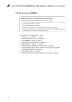
1020 Battery pack (U400)
For access, remove this FRU:
•
“1010 Base cover (U400)” on page 74
DANGER
Only use the battery specified in the parts list for your computer. Any other battery
could ignite or explode.
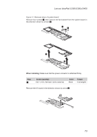
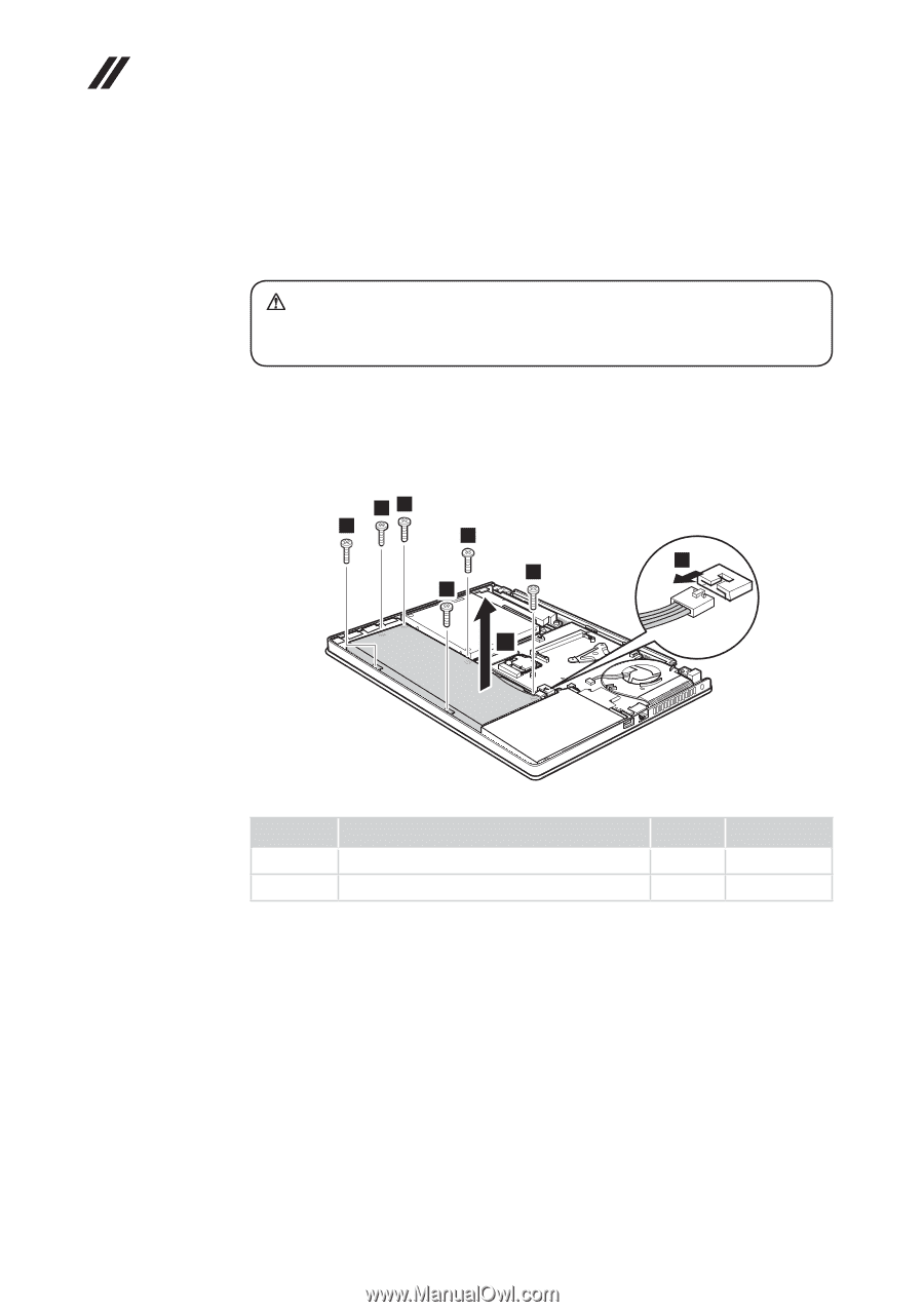
Figure 2. Removal steps of battery pack
Detach the battery pack connector in the direction shown by arrow
1
, remove
five screws
2
and one screw
3
, and then remove the battery pack
4
.
4
1
2
2
2
2
2
3
Step
Screw (quantity)
Color
Torque
2
M2 × 6 mm, flat-head, nylok-coated (5)
Black
1.6 ± 0.24 kgfcm
3
M2 × 7 mm, flat-head, nylok-coated (1)
White
1.6 ± 0.24 kgfcm
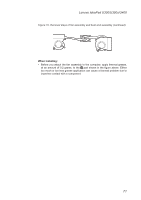
When installing:
Make sure the battery pack connector is attached firmly.