Lenovo V480c Laptop Hardware Maintenance Manual - Lenovo V480, V480c - Page 80
LCD panel, LCD cable, and hinges, Removal steps of integrated camera, When installing
 |
View all Lenovo V480c Laptop manuals
Add to My Manuals
Save this manual to your list of manuals |
Page 80 highlights
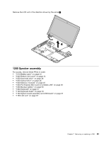
Removal steps of integrated camera Remove the integrated camera from the LCD cover as shown in the following illustration. Note: The integrated camera is stuck on the top center of the LCD cover. 1 2 When installing: Stick the integrated camera to the top center of the LCD cover and adjust the placement to ensure that the connector is attached firmly. 2030 LCD panel, LCD cable, and hinges For access, remove these FRUs in order: • "1010 Battery pack" on page 44 • "1020 Bottom slot cover" on page 44 • "1090 Keyboard" on page 51 • "1100 Keyboard bezel" on page 53 • "1160 System board assembly and USB board" on page 61 • "1190 LCD unit" on page 67 • "2010 LCD front bezel" on page 71 74 Hardware Maintenance Manual
-
 1
1 -
2
-
3
-
4
-
5
-
6
-
7
-
8
-
9
-
10
-
11
-
12
-
13
-
14
-
15
-
16
-
17
-
18
-
19
-
20
-
21
-
22
-
23
-
24
-
25
-
26
-
27
-
28
-
29
-
30
-
31
-
32
-
33
-
34
-
35
-
36
-
37
-
38
-
39
-
40
-
41
-
42
-
43
-
44
-
45
-
46
-
47
-
48
-
49
-
50
-
51
-
52
-
53
-
54
-
55
-
56
-
57
-
58
-
59
-
60
-
61
-
62
-
63
-
64
-
65
-
66
-
67
-
68
-
69
-
70
-
71
-
72
-
73
-
74
-
 75
75 -
 76
76 -
 77
77 -
 78
78 -
 79
79 -
 80
80 -
 81
81 -
 82
82 -
 83
83 -
 84
84 -
 85
85 -
86
-
87
-
88
-
89
-
90
-
91
-
92
-
93
-
94
-
95
-
96
-
97
-
98
-
99
-
100
-
101
-
102
-
103
-
104
-
105
-
106
-
107
-
108
-
109
-
110
-
111
-
112
-
113
-
114
 |
 |

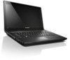
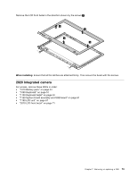
Removal steps of integrated camera
Remove the integrated camera from the LCD cover as shown in the following illustration.
Note:
The integrated camera is stuck on the top center of the LCD cover.
1
2
When installing:
Stick the integrated camera to the top center of the LCD cover and adjust the placement to
ensure that the connector is attached firmly.
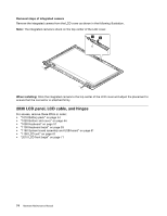
2030 LCD panel, LCD cable, and hinges
For access, remove these FRUs in order:
•
“1010 Battery pack” on page 44
•
“1020 Bottom slot cover” on page 44
•
“1090 Keyboard” on page 51
•
“1100 Keyboard bezel” on page 53
•
“1160 System board assembly and USB board” on page 61
•
“1190 LCD unit” on page 67
•
“2010 LCD front bezel” on page 71
74
Hardware Maintenance Manual