Lenovo Y70-70 Touch Laptop Hardware Maintenance Manual - Lenovo Y70-70 Touch - Page 41
Hard disk drive, Attention
 |
View all Lenovo Y70-70 Touch Laptop manuals
Add to My Manuals
Save this manual to your list of manuals |
Page 41 highlights
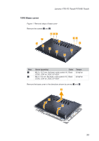
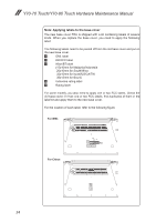
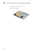
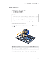
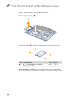
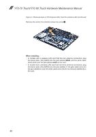
Lenovo Y70-70 Touch/Y70-80 Touch 1030 Hard disk drive For access, remove these FRUs in order: • "1010 Base cover" on page 33 • "1020 Battery pack" on page 35 Attention: • Do not drop the hard disk drive or apply any physical shock to it. The hard disk drive is sensitive to physical shock. Improper handling can cause damage and permanent loss of data. • Before removing the drive, suggest the customer to backup all the information on it if possible. • Never remove the drive while the system is operating or in suspend mode. Figure 3. Removal steps of hard disk drive Unplug the HDD connector in the direction shown by arrow 1. Remove the screws 2. 1 2 2 2 2 Step Screw (quantity) 2 M2.5 × 3.0 mm, flat-head, nylok-coated (4) HDD module to LOGIC and KB SUP BKT Color Torque Black 2.5 kgf*cm When installing: Make sure that the HDD connector is attached firmly. 37
-
 1
1 -
2
-
3
-
4
-
5
-
6
-
7
-
8
-
9
-
10
-
11
-
12
-
13
-
14
-
15
-
16
-
17
-
18
-
19
-
20
-
21
-
22
-
23
-
24
-
25
-
26
-
27
-
28
-
29
-
30
-
31
-
32
-
33
-
34
-
35
-
 36
36 -
 37
37 -
 38
38 -
 39
39 -
 40
40 -
 41
41 -
 42
42 -
 43
43 -
 44
44 -
 45
45 -
 46
46 -
47
-
48
-
49
-
50
-
51
-
52
-
53
-
54
-
55
-
56
-
57
-
58
-
59
-
60
-
61
-
62
-
63
-
64
-
65
-
66
-
67
-
68
-
69
-
70
-
71
-
72
-
73
-
74
-
75
-
76
-
77
-
78
-
79
-
80
-
81
 |
 |
