Lenovo Z40-70 Laptop Hardware Maintenance Manual - Lenovo G40-30, G40-45, G40- - Page 66
Removal steps of LCD front bezel, LCD panel, and, hinges continued
 |
View all Lenovo Z40-70 Laptop manuals
Add to My Manuals
Save this manual to your list of manuals |
Page 66 highlights
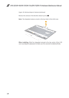
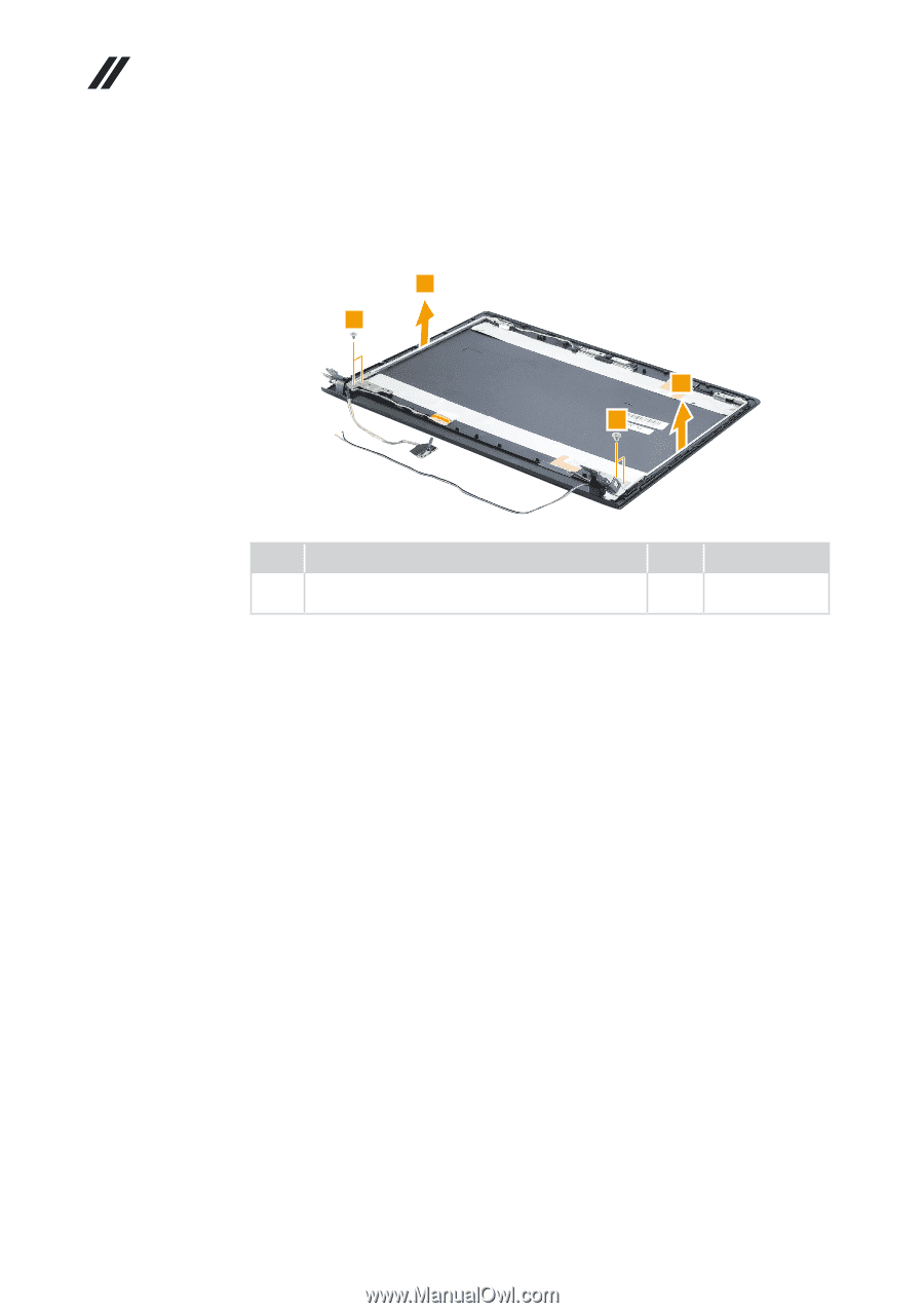
G40-30/G40-45/G40-70/G40-70m/Z40-70/Z40-75 Hardware Maintenance Manual Figure 15. Removal steps of LCD front bezel, LCD panel, and hinges (continued) Remove the screws 5. Then release the hinges in the direction shown by arrows 6. 6 5 6 5 Step Screw (quantity) 5 M2 × 3.5 mm, flat-head, nylok-coated (4) Hinge L & R to A Color Torque Black 1.5 ~ 2.0 kgf*cm 62
-
 1
1 -
2
-
3
-
4
-
5
-
6
-
7
-
8
-
9
-
10
-
11
-
12
-
13
-
14
-
15
-
16
-
17
-
18
-
19
-
20
-
21
-
22
-
23
-
24
-
25
-
26
-
27
-
28
-
29
-
30
-
31
-
32
-
33
-
34
-
35
-
36
-
37
-
38
-
39
-
40
-
41
-
42
-
43
-
44
-
45
-
46
-
47
-
48
-
49
-
50
-
51
-
52
-
53
-
54
-
55
-
56
-
57
-
58
-
59
-
60
-
 61
61 -
 62
62 -
 63
63 -
 64
64 -
 65
65 -
 66
66 -
 67
67 -
 68
68 -
 69
69 -
 70
70 -
 71
71 -
72
-
73
-
74
-
75
-
76
-
77
-
78
-
79
-
80
-
81
-
82
-
83
-
84
-
85
-
86
-
87
-
88
-
89
-
90
-
91
 |
 |
62
G40-30/G40-45/G40-70/G40-70m/Z40-70/Z40-75 Hardware Maintenance Manual
Figure 15. Removal steps of LCD front bezel, LCD panel, and
hinges (continued)
Remove the screws
5
. Then release the hinges in the direction shown by
arrows
6
.
5
5
6
6
Step
Screw (quantity)
Color
Torque
5
M2 × 3.5 mm, flat-head, nylok-coated (4)
Hinge L
& R to A
Black
1.5 ~ 2.0 kgf*cm