Lenovo Z465 Laptop Lenovo IdeaPad Z460/Z465 Hardware Maintenance Manual - Page 72
Integrated camera
 |
View all Lenovo Z465 Laptop manuals
Add to My Manuals
Save this manual to your list of manuals |
Page 72 highlights
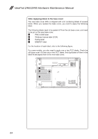
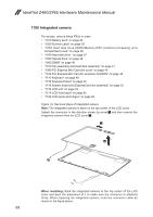
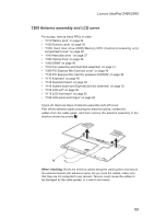
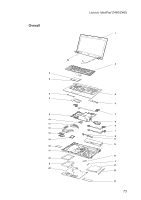
IdeaPad Z460/Z465 Hardware Maintenance Manual 1190 Integrated camera For access, remove these FRUs in order: •• "1010 Battery pack" on page 34 •• "1020 Dummy cards" on page 35 •• "1030 Hard disk drive (HDD)/Memory/CPU (Central processing unit) compartment cover" on page 36 •• "1040 Hard disk drive " on page 37 •• "1050 Optical drive" on page 39 •• "1060 DIMM" on page 40 •• "1070 Fan assembly and Heat Sink assembly" on page 41 •• "1090 PCI Express Mini Card slot cover" on page 45 •• "1100 PCI Express Mini Card for wireless LAN/WAN" on page 46 •• "1110 Keyboard" on page 48 •• "1120 Keyboard bezel" on page 50 •• "1140 System board and ExpressCard slot assembly" on page 55 •• "1150 LCD unit" on page 59 •• "1170 LCD front bezel" on page 65 •• "1180 LCD panel and hinges" on page 66 Figure 19. Removal steps of integrated camera Note: The integrated camera is stuck on the top center of the LCD cover. Detach the connector in the direction shown by arrow 1 and then remove the integrated camera from the LCD cover 2. When installing: Stick the integrated camera to the top center of the LCD cover and ajust the placement of it to make sure the connector is attached firmly. When replacing the integrated camera, route the connector cable as shown in the figure above. 68
-
 1
1 -
2
-
3
-
4
-
5
-
6
-
7
-
8
-
9
-
10
-
11
-
12
-
13
-
14
-
15
-
16
-
17
-
18
-
19
-
20
-
21
-
22
-
23
-
24
-
25
-
26
-
27
-
28
-
29
-
30
-
31
-
32
-
33
-
34
-
35
-
36
-
37
-
38
-
39
-
40
-
41
-
42
-
43
-
44
-
45
-
46
-
47
-
48
-
49
-
50
-
51
-
52
-
53
-
54
-
55
-
56
-
57
-
58
-
59
-
60
-
61
-
62
-
63
-
64
-
65
-
66
-
 67
67 -
 68
68 -
 69
69 -
 70
70 -
 71
71 -
 72
72 -
 73
73 -
 74
74 -
 75
75 -
 76
76 -
 77
77 -
78
-
79
-
80
-
81
-
82
-
83
-
84
-
85
-
86
-
87
-
88
-
89
-
90
-
91
-
92
 |
 |