LevelOne FCS-1041 Manual - Page 8
General I/O Terminal Block
 |
View all LevelOne FCS-1041 manuals
Add to My Manuals
Save this manual to your list of manuals |
Page 8 highlights
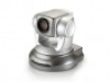
Network Camera User's Manual 4. Connect the external power supply to Network Camera Connect the attached power adapter to the DC power jack of the Network Camera. Note: Use the power adapter, 12VDC, included in the package and connect it to wall outlet for AC power. Power Socket Once you have installed the Network Camera well and powered on, the camera will do self-rotation and then the red LED will turn on and green LED will flash every second. It means that the system is booting 5. General I/O Terminal Block 1: Power 2: Digital output 3. Digital input 4. Ground 8/62
-
 1
1 -
2
-
 3
3 -
 4
4 -
 5
5 -
 6
6 -
 7
7 -
 8
8 -
 9
9 -
 10
10 -
 11
11 -
 12
12 -
 13
13 -
14
-
15
-
16
-
17
-
18
-
19
-
20
-
21
-
22
-
23
-
24
-
25
-
26
-
27
-
28
-
29
-
30
-
31
-
32
-
33
-
34
-
35
-
36
-
37
-
38
-
39
-
40
-
41
-
42
-
43
-
44
-
45
-
46
-
47
-
48
-
49
-
50
-
51
-
52
-
53
-
54
-
55
-
56
-
57
-
58
-
59
-
60
-
61
-
62
 |
 |

Network Camera User
’
s Manual
8/62
4. Connect the external power supply to Network Camera
Connect the attached power adapter to the DC power jack of the Network Camera.
Note
:
Use the power adapter, 12VDC, included in the package
and connect it to wall outlet for
AC power.
Once you have installed the Network Camera well and powered on, the camera
will do self-rotation and then the red LED will turn on and green LED will flash
every second. It means that the system is booting
5. General I/O Terminal Block
Power
Socket
1: Power
2: Digital output
3. Digital input
4. Ground