LevelOne FVS-3800 Manual - Page 11
Installation
 |
View all LevelOne FVS-3800 manuals
Add to My Manuals
Save this manual to your list of manuals |
Page 11 highlights
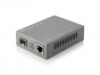
2. Installation 2-1. Cable and Hardware Installation (Web Smart Media Converters) ⇒ Wear a grounding device for electrostatic discharge ⇒ Verify that the AC-DC adapter conforms to your country AC power requirement and then insert the power plug • TP Cable ⇒ Use Cat. 5 TP cable to connect server/host or workstation to TP port of the converter ⇒ TP port supports MDI/MDI-X auto-crossover, use: straight-through cable (Cable pin-outs for RJ-45 jack 1, 2, 3, 6 to 1, 2, 3, 6) to cascade or up-link the converter to an upper layer L2/L3 switch or server/host/workstation ⇒ TP Cable Limitations: Cat. 5 and up to 100m • Fiber Cable ⇒ Use fiber cable to connect FX port of an upper layer converter ⇒ Fiber Cable Limitations: SC Converter Models Multi-mode Half-duplex Multi-mode Full-duplex Single-mode Half-duplex Single-mode Full-duplex 412m 2Km 412m 10/30/50Km Table 2-1 Note: The other side of the fiber cable plugged into the converter's RX connector at the near end should plug into the FX device's TX connector at the far end, and vice versa. 2-2. Cable and Hardware Installation (Web Smart Media Converter Chassis) 2.5mm DC Receptacle 2.5mm 1A@+5V for each slot ⇒ The slide-in Media Converters and Converter Rack should be supplied only from the same source; both Media Converters and Rack are built to match each other at dimensions, DC power DC receptacle is 2.5mm wide that jack, DC receptacle and power safety. matches and conforms to the Media ⇒ Turn off the 19" converter rack power. Converter 2.5mm DC jack's central ⇒ Verify the Media Converter is right for this Rack and post. Do not install any improper unit locate +5VDC power jack on converter back, and or model of the Media Converter. carefully slide in and plug to match 19" rack slot +5VDC receptacle. 5
-
 1
1 -
2
-
3
-
4
-
5
-
 6
6 -
 7
7 -
 8
8 -
 9
9 -
 10
10 -
 11
11 -
 12
12 -
 13
13 -
 14
14 -
 15
15 -
 16
16 -
17
-
18
-
19
-
20
-
21
-
22
-
23
-
24
-
25
-
26
-
27
-
28
-
29
-
30
-
31
-
32
-
33
-
34
-
35
-
36
-
37
-
38
-
39
-
40
-
41
-
42
-
43
-
44
-
45
-
46
-
47
-
48
 |
 |
