LevelOne IES-0852 Manual - Page 10
Connecting to Your Network
 |
View all LevelOne IES-0852 manuals
Add to My Manuals
Save this manual to your list of manuals |
Page 10 highlights
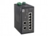
Connecting to Your Network Cable Type & Length It is necessary to follow the cable specifications below when connecting the switch to your network. Use appropriate cables that meet your speed and cabling requirements. Cable Specifications Speed 10Base-T 100Base-TX 100Base-FX Connector RJ-45 Port Speed Half/Full Duplex 10/20 Mbps RJ-45 100/200 Mbps ST, SC 100/200 Mbps Cable 2-pair UTP/STP Cat. 3, 4, 5 2-pair UTP/STP Cat. 5 MMF (50 or Max. Distance 100 m 100 m 2 km 100Base-FX ST, SC 100/200 Mbps 20, 40, or 75 km Cabling Step 1: First, ensure the power of the switch and end devices are turned off. Always ensure that the power is off before any installation. Step 2: Prepare cable with corresponding connectors for each type of port in use. Step 3: Consult Cable Specifications Table on previous page for cabling requirements based on connectors and speed. Step 4: Connect one end of the cable to the switch and the other end to a desired device. Step 5: Once the connections between two end devices are made successfully, turn on the power and the switch is operational. IES-0852 User Manual Page 10
-
 1
1 -
2
-
3
-
4
-
 5
5 -
 6
6 -
 7
7 -
 8
8 -
 9
9 -
 10
10 -
 11
11 -
 12
12 -
 13
13 -
 14
14 -
 15
15 -
16
-
17
-
18
-
19
-
20
-
21
 |
 |
