LevelOne IES-1081 Manual - Page 5
Quick Start Guide
 |
View all LevelOne IES-1081 manuals
Add to My Manuals
Save this manual to your list of manuals |
Page 5 highlights
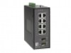
Quick Start Guide This quick start guide describes how to install and use the Hardened Managed Ethernet Switch. This is the switch of choice for harsh environments constrained by space. Physical Description The Port Status LEDs and Power Inputs Front Panel Rear Panel Terminal Block + 12 48VDC PW1 Power Ground + 12 48VDC PW2 Power Ground Earth Ground Relay Output 1A @ 24VDC Relay Alarm warning signal disable for following: 1. The relay contact closes if Power1 and Power2 are both failed but Power3 on 2. The relay contact closes if Power3 is failed but Power1 and Power2 are both on IES-1081 User Manual Page 5
-
 1
1 -
 2
2 -
 3
3 -
 4
4 -
 5
5 -
 6
6 -
 7
7 -
 8
8 -
 9
9 -
 10
10 -
 11
11 -
12
-
13
-
14
-
15
-
16
-
17
-
18
-
19
-
20
-
21
-
22
-
23
-
24
-
25
-
26
-
27
-
28
-
29
-
30
-
31
-
32
-
33
-
34
-
35
-
36
-
37
-
38
-
39
-
40
-
41
-
42
-
43
-
44
-
45
-
46
-
47
-
48
-
49
-
50
-
51
-
52
-
53
-
54
-
55
-
56
-
57
-
58
-
59
-
60
-
61
-
62
-
63
-
64
-
65
-
66
-
67
-
68
-
69
-
70
-
71
-
72
-
73
-
74
-
75
-
76
-
77
-
78
-
79
-
80
-
81
-
82
-
83
-
84
-
85
-
86
-
87
-
88
-
89
-
90
-
91
-
92
-
93
-
94
-
95
-
96
-
97
-
98
-
99
-
100
-
101
-
102
-
103
-
104
-
105
-
106
-
107
-
108
-
109
-
110
-
111
-
112
-
113
-
114
-
115
-
116
-
117
-
118
-
119
-
120
-
121
-
122
-
123
-
124
-
125
-
126
-
127
-
128
-
129
-
130
-
131
-
132
-
133
-
134
-
135
-
136
-
137
-
138
-
139
-
140
-
141
-
142
-
143
-
144
-
145
-
146
-
147
-
148
-
149
-
150
 |
 |

IES-1081 User Manual
Page 5
Quick Start Guide
This quick start guide describes how to install and use the Hardened Managed Ethernet
Switch. This is the switch of choice for harsh environments constrained by space.
Physical Description
The Port Status LEDs and Power Inputs
Front Panel
Rear Panel
Terminal Block
PW1
+
12
48VDC
Power Ground
PW2
+
12
48VDC
Power Ground
Earth Ground
Relay Output
1A @ 24VDC
Relay Alarm warning signal disable for following:
1.
The relay contact closes if Power1 and Power2 are both failed but Power3 on
2.
The relay contact closes if Power3 is failed but Power1 and Power2 are both on