LevelOne PFE-1014R Quick Install Guide - Page 2
PFE-1001R/1011R and PFE-1004R/1014R Connection
 |
View all LevelOne PFE-1014R manuals
Add to My Manuals
Save this manual to your list of manuals |
Page 2 highlights
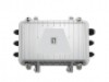
Hybrid Fiber Cable Mdoel No Hybrid Cable Conductor Gauge 450M 700M 1KM 2KM PFE-1001T PFC-0112 12 AWG 50W 45W 40W 20W PFE-1001T PFC-0118 18 AWG 40W 20W 10W - PFE-1101T PFC-0112 12 AWG 60W 55W 50W 28W PFE-1101T PFC-0118 18 AWG 50W 28W 18W - Step 1: PFE-1001T /1101T Connections A. Connect PFE-1001T/1101T RJ45 LAN port to the PC or Notebook using a Category 5 LAN cable as the above connections. B. Connect the AC-DC Power Adaptor to the PFE-1001T/1101T DC port (back panel). C. Connect the Fiber cable to the PFE-1001T/1101T Fiber port. D. Connect the Copper cable to the PFE-1001T/1101T DC Terminal Block (front panel) Step 2: PFE-1001R/1011R and PFE-1004R/1014R Connections E. Connect PFE-1001R/1011R and PFE-1004R/1014R RJ45 LAN port to the PoE IP CAM using a Category 5 LAN cable as the above connections.(PFE-1004R/1014R PoE DiP Switch need On) F. Connect the Fiber cable to the PFE-1001R/1011R Fiber port. G. Connect the Copper cable to the PFE-1001R/1011R DC Terminal Block (front panel) Step 3: POWER ON and Run H. Turn the AC-DC Power Adaptor ON. I. Run the PC IP CAM monitoring software. Ordering Information Model Specification PFE-1001T PoE Extender over Hybrid Fiber, Transmitter, 65W PFE-1101T PoE Extender over Hybrid Fiber, Transmitter, 120W PFE-1001R PoE Extender over Hybrid Fiber, Receiver with 1 PoE Output PFE-1004R PoE Extender over Hybrid Fiber, Receiver with 4 PoE Output PFE-1011R PoE Extender over Hybrid Fiber, Outdoor Receiver with 1 PoE Output PFE-1014R PoE Extender over Hybrid Fiber, Outdoor Receiver with 4 PoE Outputs PFC-0112 Hybrid Fiber Cable, 12 AWG PFC-0118 Hybrid Fiber Cable, 18 AWG
-
 1
1 -
 2
2
 |
 |
