LiftMaster 3585 3585 Elite Series Manual - Page 6
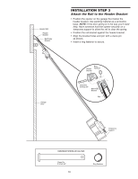
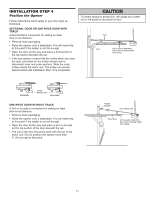
ASSEMBLY, STEP 1 Attach the Rail to the Motor Unit, STEP 2 Set the Belt Tension - belt drive garage door opener
 |
View all LiftMaster 3585 manuals
Add to My Manuals
Save this manual to your list of manuals |
Page 6 highlights
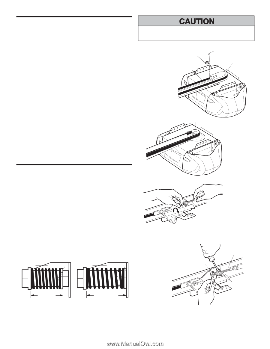
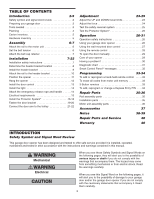
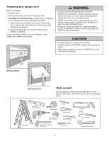
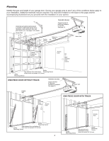
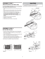
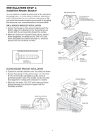
ASSEMBLY STEP 1 Attach the Rail to the Motor Unit To avoid installation difficulties, do not run the garage door opener until instructed to do so. • Remove the bolt and lock nut from the top of the motor unit. • Place rail onto the bolt mounted on the motor unit and align the back hole with the hole in the top of the unit. • Fasten rail with the washered bolt and lock nut previously removed. Tighten securely. Remember to use only these bolts/fasteners! Any other bolts/fasteners will cause serious damage to the opener. The Chamberlain Group, Inc. Liftmaster Synchro Drive • Cut tape from rSapirlin,gbTeroltlleaynNdut sAtsysermofbolyam. 3/5/92 - 5/16 /92 - 5/21/92 - 6/2/92 • REMOVE STY6R/1O1/9F2OAM. • Position belt over the motor unit sprocket. To avoid SERIOUS damage to opener, ONLY use bolts/fasteners mounted in top of motor unit. Lock Nut Rail Hole Washered Bolt 5/16"-18x1/2" Styrofoam Motor unit Sprocket ASSEMBLY STEP 2 Set the Belt Tension • By hand, thread the spring trolley nut on the threaded shaft until it is finger tight against the trolley (Figure 1). Do not use any tools. • Insert a screwdriver tip into one of the nut ring slots and brace it firmly against the trolley (Figure 2). • Place a 7/16" open end wrench on the square end. Rotate about 1/4 turn until the spring releases and snaps the nut ring against the trolley (Figure 3). This extends the spring for optimum belt tension. Figure 1 Trolley Nut Ring Trolley Nut Ring Trolley Threaded Shaft Spring/Trolley Nut Square End Nut Ring Trolley Threaded Shaft BEFORE 1" (2.5 cm) Figure 3 AFTER RELEASE 1-1/4" (3.18 cm) Figure 2 Nut Ring Slots 6
-
 1
1 -
 2
2 -
 3
3 -
 4
4 -
 5
5 -
 6
6 -
 7
7 -
 8
8 -
 9
9 -
 10
10 -
 11
11 -
 12
12 -
13
-
14
-
15
-
16
-
17
-
18
-
19
-
20
-
21
-
22
-
23
-
24
-
25
-
26
-
27
-
28
-
29
-
30
-
31
-
32
-
33
-
34
-
35
-
36
-
37
-
38
-
39
-
40
 |
 |