LiftMaster 3900 3900PLD Manual - Page 13
Installation Step 8
 |
View all LiftMaster 3900 manuals
Add to My Manuals
Save this manual to your list of manuals |
Page 13 highlights
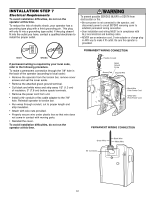
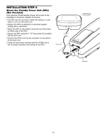
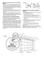
INSTALLATION STEP 8 Mount the Standby Power Unit (SPU) (Not Provided) If the optional 475LM Standby Power Unit is part of this installation it should be installed at this time. • The SPU can be mounted to either the ceiling or a wall within 3' (.9 m) of the motor unit. • Position the SPU as desired to a structural support (ceiling joist or wall stud). • Attach the SPU to the support using the mounting holes on either side of the SPU. • Secure the SPU using the 1-1/2" lag screws (2) provided with the SPU unit. • Connect the SPU cord into the connector on the bottom of the motor unit. • Follow all instructions included with the 475LM unit to test for proper operation and testing of the SPU. SPU Cord 475LM Standby Power System Connector 13
-
 1
1 -
2
-
3
-
4
-
5
-
6
-
7
-
 8
8 -
 9
9 -
 10
10 -
 11
11 -
 12
12 -
 13
13 -
 14
14 -
 15
15 -
 16
16 -
 17
17 -
 18
18 -
19
-
20
-
21
-
22
-
23
-
24
-
25
-
26
-
27
-
28
-
29
-
30
-
31
-
32
 |
 |

13
INSTALLATION STEP 8
Mount the Standby Power Unit (SPU)
(Not Provided)
If the optional 475LM Standby Power Unit is part of this
installation it should be installed at this time.
•
The SPU can be mounted to either the ceiling or a wall
within 3' (.9 m) of the motor unit.
•
Position the SPU as desired to a structural support
(ceiling joist or wall stud).
•
Attach the SPU to the support using the mounting holes
on either side of the SPU.
•
Secure the SPU using the 1-1/2" lag screws (2) provided
with the SPU unit.
•
Connect the SPU cord into the connector on the bottom
of the motor unit.
•
Follow all instructions included with the 475LM unit to
test for proper operation and testing of the SPU.
SPU Cord
Connector
475LM Standby
Power System