LiftMaster APT APT LOGIC 3 Manual - Page 13
Standard Power & Control Connection Diagrams
 |
View all LiftMaster APT manuals
Add to My Manuals
Save this manual to your list of manuals |
Page 13 highlights
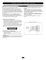
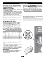
STANDARD POWER & CONTROL CONNECTION DIAGRAMS Radio Control (24V DC only) CPS-L & CPS-LN4 R3 R2 R1 Sensing Edge Timer Defeat Switch Maintenance Alert LED (RD) (WH) Open Close Stop Open/Close Single Button OPEN CLOSE STOP 3-Button Station Remove Jumper To Install External Interlock Single Phase Power Wiring Line Power 115 Vac Single Phase Hot Neutral Gnd 13
-
 1
1 -
2
-
3
-
4
-
5
-
6
-
7
-
 8
8 -
 9
9 -
 10
10 -
 11
11 -
 12
12 -
 13
13 -
 14
14 -
 15
15 -
 16
16 -
 17
17 -
 18
18 -
19
-
20
-
21
-
22
-
23
-
24
-
25
-
26
-
27
-
28
-
29
-
30
-
31
-
32
-
33
-
34
-
35
-
36
 |
 |

13
STANDARD POWER & CONTROL CONNECTION DIAGRAMS
Open
Close
Stop
Maintenance
Alert LED
Open/Close
Single Button
(WH)
(RD)
Sensing Edge
CPS-L &
CPS-LN4
Timer Defeat
Switch
R1
R2
R3
Radio Control
(24V DC only)
Remove Jumper
To Install External
Interlock
3-Button
Station
OPEN
CLOSE
STOP
Neutral
Hot
Gnd
Single Phase Power Wiring
Line Power
115 Vac
Single Phase