LiftMaster CAPXLV LiftMaster K-41-0117-000 Instruction Sheet - English French - Page 1
LiftMaster CAPXLV Manual
 |
View all LiftMaster CAPXLV manuals
Add to My Manuals
Save this manual to your list of manuals |
Page 1 highlights
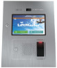
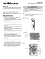
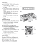
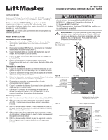
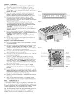
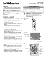
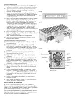
K41-0117-000 TOUCHSCREEN DISPLAY AND DOOR KIT INTRODUCTION The K41-0117-000 Touchscreen Display and Door Kit is a replacement for the Connected Access Portal - High Capacity (Models CAPXL and CAPXLV). K41-0117-000 Carton Inventory (Figure A): Fully assembled CAPXL door with LCD display and touchscreen assembly, display gasket, camera window, nut 6-32 (9), cable tie (8), installation instructions. NOTE: New K001D8439 Power/Internet board will ship in separate box. INSTALLATION INSTRUCTIONS Disconnect and remove control board 1. Disconnect power to the CAPXL. Remove the PWR INPUT terminal block from the Power/Internet Board (Figure B). 2. Disconnect the USB, Ethernet, computer power, and data cables from the control board (Figure C). 3. Cut the cable tie holding the data cable to the control board. Do NOT cut the data cable. 4. Remove the 4 locknuts securing the control board to the CAPXL door. 5. Carefully pull the control board away from the faceplate. Disconnect the audio cable from the control board. Set aside the control board. Unplug connectors 6. Cut the 2 cable ties securing the harness to the left side of the display bracket. Do NOT cut the cables. 7. Remove the 2 mounting screws from the light sensor board and allow the board to dangle by the cables. 8. Remove the 2 locknuts from the postal lock lever-switch. Remove the postal lock lever-switch. Remove the plastic spacers. 9. Disconnect the Touch Panel connector from the Power/Internet board (Figure B). 10. Cut the connector off of the Touch Panel harness and slide the remaining wire entirely through the braided sleeve. 11. Unplug the backlight connector (Red/White wire) from the Power/ Internet board and pull the wire entirely through the braided sleeve. Discard the backlight connector. Remove hardware 12. Remove the 2 screws securing the microphone to the CAPXL door. 13. Remove the 4 nuts securing the speaker to the CAPXL door, carefully pull speaker from door and set inside enclosure. 14. Remove 1 wingnut securing the postal lock cover or remove 4 nuts holding postal lock in place (if equipped). Remove postal lock/cover. 15. Remove 4 locknuts securing card reader bracket in place, remove card reader (if equipped). Carefully remove reader bracket/cover. 16. Remove 1 wingnut securing camera bracket in place. Carefully remove camera/bracket and set inside enclosure. To prevent possible SERIOUS INJURY or DEATH, disconnect electric power to operator BEFORE installing. ALL installations and electrical connections MUST be made by a qualified individual. WARNING: This product can expose you to chemicals including lead, which are known to the State of California to cause cancer or birth defects or other reproductive harm. For more information go to www.P65Warnings.ca.gov. Figure A CAPXL door with LCD display and touchscreen assembly Figure B Power/Internet Board Backlight Power connector location Touch Panel connector location OTS Backlit ON Figure C ON PWR INPUT terminal block location Light sensor board Data cables Braided sleeve USB Computer power Ethernet Postal lock Speaker Nuts
-
 1
1 -
 2
2 -
 3
3 -
 4
4 -
 5
5 -
 6
6 -
 7
7 -
8
 |
 |