LiftMaster CAPXLV Quick Start Guide - English French Spanish - Page 2
Setup, Installation - capxl video
 |
View all LiftMaster CAPXLV manuals
Add to My Manuals
Save this manual to your list of manuals |
Page 2 highlights
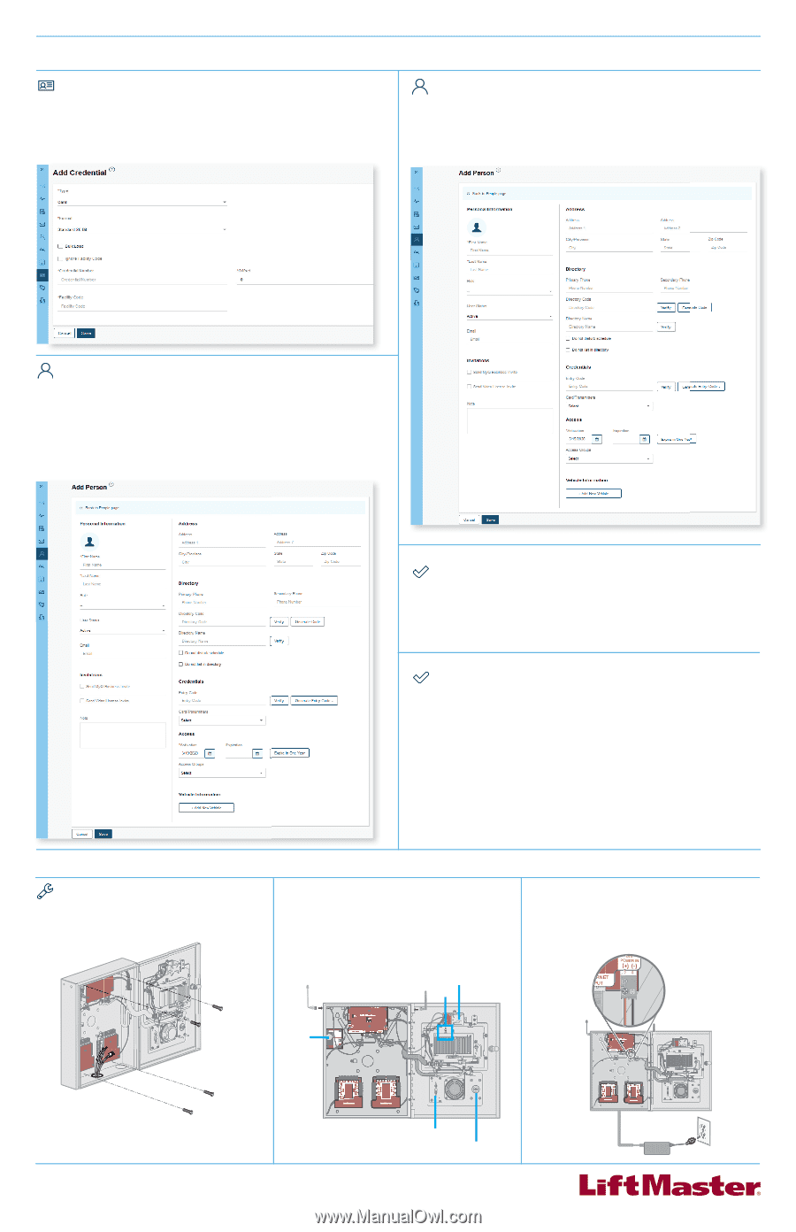
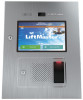
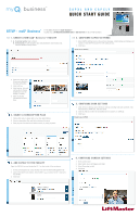
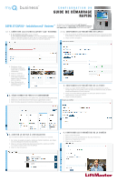
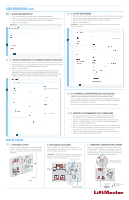
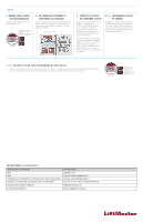
SETUP (CONTINUED) 7. ADD CREDENTIALS 1. On the left navigation bar, click Credentials. 2. Click the Add Credential button to add transmitters, cards, etc. Individually or in bulk to the Facility. 3. Click Save. NOTE: A credential must be associated to a person for it to be active. See Step 8. 9. ADD PERSON 1. From the People menu, click the Add Person Button. 2. Add staff, residents, and vendors. This includes phone number(s), entry code(s), credentials, group(s), and activation dates. 3. Click Save. NOTE: A person must be in a group to access any entrances in the community. 8. INVITE FACILITY OWNER AND ADMINISTRATORS 1. From the People menu, click the Add Person button. 2. Enter first and last name. You may enter other optional information on this page (Email, Role, Address, Directory, Credentials, Access, and Vehicles). 3. Click Save. 4. The person will receive an email invite to log into the Facility with rights determined by their role. The ranking of roles, from highest are Dealer Owner and Facility Owner, which have the most control, followed by Dealer Manager, Facility Manager, Dealer Tech, and Access Manager. 10. CONFIRM SETUP PRIOR TO INSTALLATION Confirm settings match those in myQ® Business™. Make a test phone call (this can be done by calling a name in the directory or using the SIP test function under Network in the CAPXLV Admin mode. Disconnect power and Internet after settings have been confirmed. 11. VERIFY VIDEO CAMERA OPERATION 1. Turn on CAPXLV Admin mode, Locate and turn on DIP Switch 1 (located on Power & Internet board). 2. Make a test phone call using the SIP test function under Network > Test Sip. Enter a phone number and press the green phone icon. 3. Open the Audio/Video tab to confirm the video feed is working. 4. Turn off CAPXL Admin mode. Locate and turn off DIP Switch 1 (located on Power & Internet board). 5. Perform multiple access events at the CAPXLV and confirm archived video clips appear in the Activity Log. INSTALLATION 1. INSTALL CAPXLV Remove knock outs as required and mount the CAPXLV to a pedestal, a flat solid surface, or into the optional trim kit and back box accessory (CAPXLTK). 2. INSTALL ACCESSORIES Install radio and Wi-Fi antennas, postal lock, optional card reader, and optional quick call input board as required. NOTE: CAPXLV includes a camera.CAPXL retrofit accessory kit (CAPXLCAM) for CAPXL or for replacement. CAPXLCAM (optional) Wi-Fi LPEXP (optional) 3. CONNECT POWER AND GROUND Route power wires from included Power Supply to CAPXLV and plug transformer into a 120 Vac outlet. Confirm CAPXLV powers on. Connect ground lug to earth ground. See the full manual for more information. POWER INPUT Power/Internet Board Card Reader (optional) Postal Lock (optional) Power Supply 120 Vac Dedicated Outlet
-
 1
1 -
 2
2 -
 3
3 -
 4
4 -
 5
5 -
 6
6 -
 7
7 -
 8
8 -
9
-
10
-
11
-
12
 |
 |