LiftMaster CSW24UL Installation Manual - Page 33
EXPANSION BOARD, Expansion board overview
 |
View all LiftMaster CSW24UL manuals
Add to My Manuals
Save this manual to your list of manuals |
Page 33 highlights
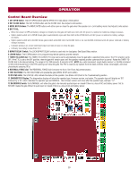
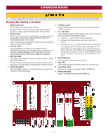
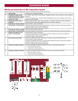
EXPANSION BOARD l To AVOID damaging the circuit board, relays or accessories, DO NOT connect more than 42 Vdc (32 Vac) to the AUX relay contact terminal blocks. Expansion board overview 1. QUICK CLOSE switch: 6. EYE/EDGE switches: OFF: No change to the gate's normal operation. ON: When CLOSE EYES/Interrupt loop is deactivated it causes an opening or a stopped gate to close (ignores the Timer-to-Close). Set the EYE/EDGE switches as needed to obtain the desired OPEN or CLOSE functionality. 7. 1, 2, and 3 LEDs: 2. AC FAIL switch: LEDs indicating the status of the EYE/EDGE inputs. Also used to check OPEN: Loss of AC power will cause the gate to open approximately 15 the firmware version of the expansion board: seconds after AC power fail and remain OPEN until AC power is 1. Locate the 1, 2, and 3 LEDs on the expansion board. restored (enabling the Timer-to-Close). 2. Disconnect AC/DC power to the main control board for 15 BATT: With loss of AC power, gate will remain in present position and seconds. operator is powered from batteries. 3. Connect power. The 1, 2, and 3 LEDs will flash in sequence until 3. EXIT FAIL switch: the main control board firmware revision is displayed. When the When set to OPEN, if the EXIT plug-in loop detector (Model LOOPDETLM) detects a fault, then the gate will open and remain open until fault is cleared. When set to CLOSE, then plug-in EXIT loop detector faults are ignored (EXIT loop is faulted and inoperative). 4. ANTI-TAIL switch: OFF: When CLOSE EYES/Interrupt loop is activated it causes a closing gate to stop and reverse. green POWER LED glows solid the LED 1 will flash the version number, then stop, then the LED 2 will flash the revision number (for example: For version 5.1 when the green POWER LED is solid the LED 1 will flash 5 times, then stop, then the LED 2 will flash once). 8. MAIN BOARD input: Input Connection for the main board connector. ON: When CLOSE EYES/Interrupt loop is activated it causes a closing 9. Input LEDs: gate to pause. Once the vehicle is clear the gate will continue to close. LEDs indicating the status of the SBC, OPN, CLS, and STP inputs. 5. AUX RELAY switches: 10. Loop detector inputs: Set the AUX RELAY switches as needed to obtain the desired function Inputs for the Plug-In Loop Detectors (Model LOOPDETLM) as shown on the following page. 11. Wireless edge input: Input for the Wireless Edge Kit (Model LMWEKITU) 33
-
 1
1 -
2
-
3
-
4
-
5
-
6
-
7
-
8
-
9
-
10
-
11
-
12
-
13
-
14
-
15
-
16
-
17
-
18
-
19
-
20
-
21
-
22
-
23
-
24
-
25
-
26
-
27
-
 28
28 -
 29
29 -
 30
30 -
 31
31 -
 32
32 -
 33
33 -
 34
34 -
 35
35 -
 36
36 -
 37
37 -
 38
38 -
39
-
40
-
41
-
42
-
43
-
44
-
45
-
46
-
47
-
48
-
49
-
50
-
51
-
52
-
53
-
54
-
55
-
56
 |
 |