LiftMaster DH DJ LOGIC 2 ADDENDUM Manual - Page 1
LiftMaster DH Manual
 |
View all LiftMaster DH manuals
Add to My Manuals
Save this manual to your list of manuals |
Page 1 highlights
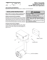
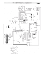
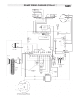
Motor Assembly Replacement Kit for 1/2 HP FDO-Line Operators APPLICATION REQUIREMENTS: Replacement of Motor and/or its components for a Model 1/2 HP FDO Operator. INSTALLATION INSTRUCWTIOANRSNING WARNING NOTE: Refer to the Owner's Manual supplied with the operator for all mounting and wiring instructions. REMOVE EXISTING MOTOR ASSEMBLY: Disconnect the wire connections to the motor. Remove the brake cover and locate the (4) flange nuts securing the brake assembly to the motor. Remove the (4) flange nuts CAUTION and the break assembly and set off to the side. Remove the (2) bolts securing the motor to the frame and lower the front of the motor and slide the motor from the frame. DISCONNECT POWER AT THE FUSE BOX BEFORE PROCEEDING. IF NECESSARY REMOVE THE OPERATOR FROM ITS MOUNTED POSITION. OPERATOR MUST BE PROPERLY GROUNDED AND CONNECTED IN ACCORDANCE WITH LOCAL ELECTRICAL CODES. NOTE: THE OPERATOR SHOULD BE ON A SEPARATE FUSED LINE OF ADEQUATE WARNING CAPACITY. ALL ELECTRICAL CONNECTIONS MUST BE MADE BY A QUALIFIED INDIVIDUAL. MOUNTING NEW MOTOR ASSEMBLY: To install the motor assembly, follow the steps outlined above in reverse order. Reconnect the wires to the motor, referring to the owners manual and wiring diagrams on pages 2 and 3. BRAKE COVER FLANGE NUTS MOTOR ASSEMBLY
-
 1
1 -
 2
2 -
 3
3 -
 4
4
 |
 |