LiftMaster EL1SS EL1SS Repair Parts Instructions Manual - Page 4
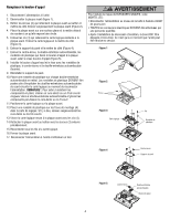
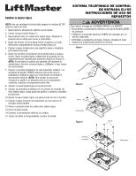
Replace the Call Button
 |
View all LiftMaster EL1SS manuals
Add to My Manuals
Save this manual to your list of manuals |
Page 4 highlights
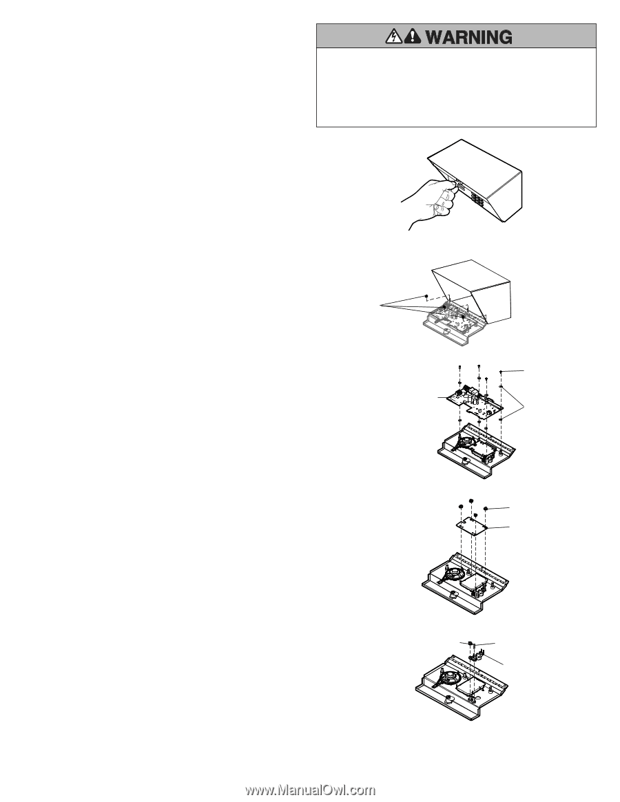
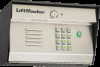
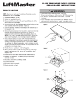
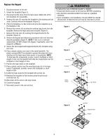
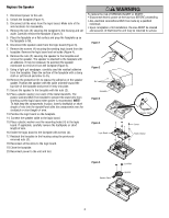
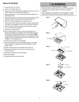
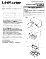
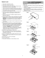
Replace the Call Button 1. Disconnect power to the unit. 2. Unlock the faceplate (Figure 1). 3. Remove the nuts (3) securing the faceplate to the housing and set aside. Carefully remove the faceplate (Figure 2). 4. Place the faceplate on a flat surface and prop the faceplate up so the faceplate is flat. 5. Remove the screws (4) securing the existing logic board from the faceplate. Remove the logic board and set aside (Figure 3). 6. Remove the keypad bracket and set aside (Figure 4). 7. Remove the lock nut, stand-off, and plastic washers securing the call button to the faceplate. Discard the old call button (Figure 5). 8. Install the new call button and secure with the plastic washers, lock nut, and stand-off (provided). 9. Reinstall the keypad bracket. 10. Place a plastic washer over each of the metal standoffs. The plastic washers MUST be installed to prevent the stand offs from shorting out the logic board when power is reconnected. NOTE: To help keep the components in place, insert a toothpick or short length of wire into the standoff and slide the components over the toothpick or short length of wire. 11. Position the logic board on the faceplate. 12. Place a plastic washer over the mounting holes (4) in the logic board. If applicable, carefully remove the toothpicks or short length of wire. 13. Fasten the logic board to the faceplate with screws (4). 14. Reattach the faceplate to the housing using the previously removed nuts (3). 15. Reconnect all the wires to the logic board. 16. Close the faceplate. 17. Reconnect power to the unit and test. To reduce the risk of SERIOUS INJURY or DEATH: • Disconnect electric power at the fuse box BEFORE proceeding. • ALL electrical connections MUST be made by a qualified individual. • Upon completion of kit installation, the area MUST be cleared and secured. At that time the unit may be returned to service. Figure 1 Figure 2 Nut Figure 3 Logic Board Screw Plastic Washer Figure 4 Lock Nut Keypad Bracket Figure 5 Lock Nut Standoff Call Button 4
-
 1
1 -
 2
2 -
 3
3 -
 4
4 -
 5
5 -
 6
6 -
 7
7 -
 8
8 -
 9
9 -
 10
10 -
11
-
12
 |
 |