LiftMaster HCT HCT501130 Manual - Page 17
INSTRUCTIONS FOR OPTIONAL SYSTEMS, 3-BUTTON STATION, QCC is designed for slide gate operators only
 |
View all LiftMaster HCT manuals
Add to My Manuals
Save this manual to your list of manuals |
Page 17 highlights
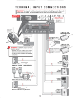
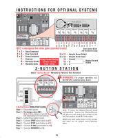
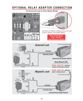
INSTRUCTIONS FOR OPTIONAL SYSTEMS CENTER SAFETY EXIT QCC AB OPEN STOP CLOSE MAGLOCK ALARM ARMED M/S LINK SENSOR ALARM QCC W4 OPEN GBAA B SMTOSPLINKCLOSE MAGLOCK ALARM ARMED M/S LINK ALARM SENSOR DC-BACKUP SYSTEM ON SENSORS 1 3 1 3 REVERSE SENSOR TIMER 60 3 OFF OPEN LEFT 1 3 ON OPEN RIGHT COMMAND PROCESSED FIRE DEPT. STRIKE OPEN RADIO RECEIVER GATE LOCKED EXIT LOOP SAFETY LOOP CENTER LOOP RESET MOTOR CLOSE STOP OPEN POWER OVERLOAD MADE IN USA 1 2 3 4 5 6 7 8 9 10 11 12 13 14 15 16 CENTER SAFETY EXIT N.O. Gnd N.C. Gnd N.O. Gnd Com N.C. N.O. Com N.O. N.C. Gnd Gnd B A QCC is designed for slide gate operators only! Omni Option Board 1 & 2 - Open Command see Accessories page 3 & 4 - Stop Command 10 & 11 - Burglar Alarm Output 5 & 6 - Close Command 12 & 13 - Burglar Alarm Input 7 - Common Relay Contact Rating 8 - Normally Closed 0.5 Amp - 125 Vac 9 - Normally Open 1 Amp - 24 Vdc 14 - Ground 15 - B 16 - A Master/Second RS485 3-BUTTON STATION Omni "Option Board" Needed to Perform This Function OPEN STOP CLOSE WARNING: For proper operation, cut W4 BEFORE installing option board. CENTER SAFETY EXIT 123456 N.O. N.C. N.O. Com 3-Button Station (OPEN-STOP-CLOSE) Step 1 - Disconnect power. W4 Step 2 - Cut jumper wire #W4. Note: If this jumper is not cut, the stop button will not function. Step 3 - Install Omni option board. Step 4 - Connect OPEN push button to # 1 . Step 5 - Connect STOP push button to # 3 . Step 6 - Connect CLOSE push button to # 5 . Step 7 - Connect COMMON to # 6 . QCC W4 OPEN GBAA B SMTOSPLINKCLOSE MAGLOCK ALARM ARMED M/S LINK ALARM SENSOR DC-BACKUP SYSTEM ON SENSORS 1 3 1 3 REVERSE SENSOR TIMER 60 3 OFF OPEN LEFT 1 3 ON OPEN RIGHT COMMAND PROCESSED FIRE DEPT. STRIKE OPEN RADIO RECEIVER GATE LOCKED EXIT LOOP SAFETY LOOP CENTER LOOP RESET MOTOR CLOSE STOP OPEN POWER OVERLOAD MADE IN USA CENTER SAFETY EXIT Note: If using the Master/Second board configuration, unplug the Master/Second link plug on main board and connect it into the Omni option board M/S link socket. Make sure each push button is dry contact and there are no jumper wires between them. SENSOR ALARM 15
-
 1
1 -
2
-
3
-
4
-
5
-
6
-
7
-
8
-
9
-
10
-
11
-
 12
12 -
 13
13 -
 14
14 -
 15
15 -
 16
16 -
 17
17 -
 18
18 -
 19
19 -
 20
20 -
 21
21 -
 22
22 -
23
-
24
-
25
-
26
-
27
-
28
-
29
-
30
-
31
-
32
-
33
-
34
-
35
-
36
 |
 |
