LiftMaster HDSL24UL Installation Manual - English - Page 37
Wiring Accessories to the Expansion Board, Single Button Control, SBC
 |
View all LiftMaster HDSL24UL manuals
Add to My Manuals
Save this manual to your list of manuals |
Page 37 highlights
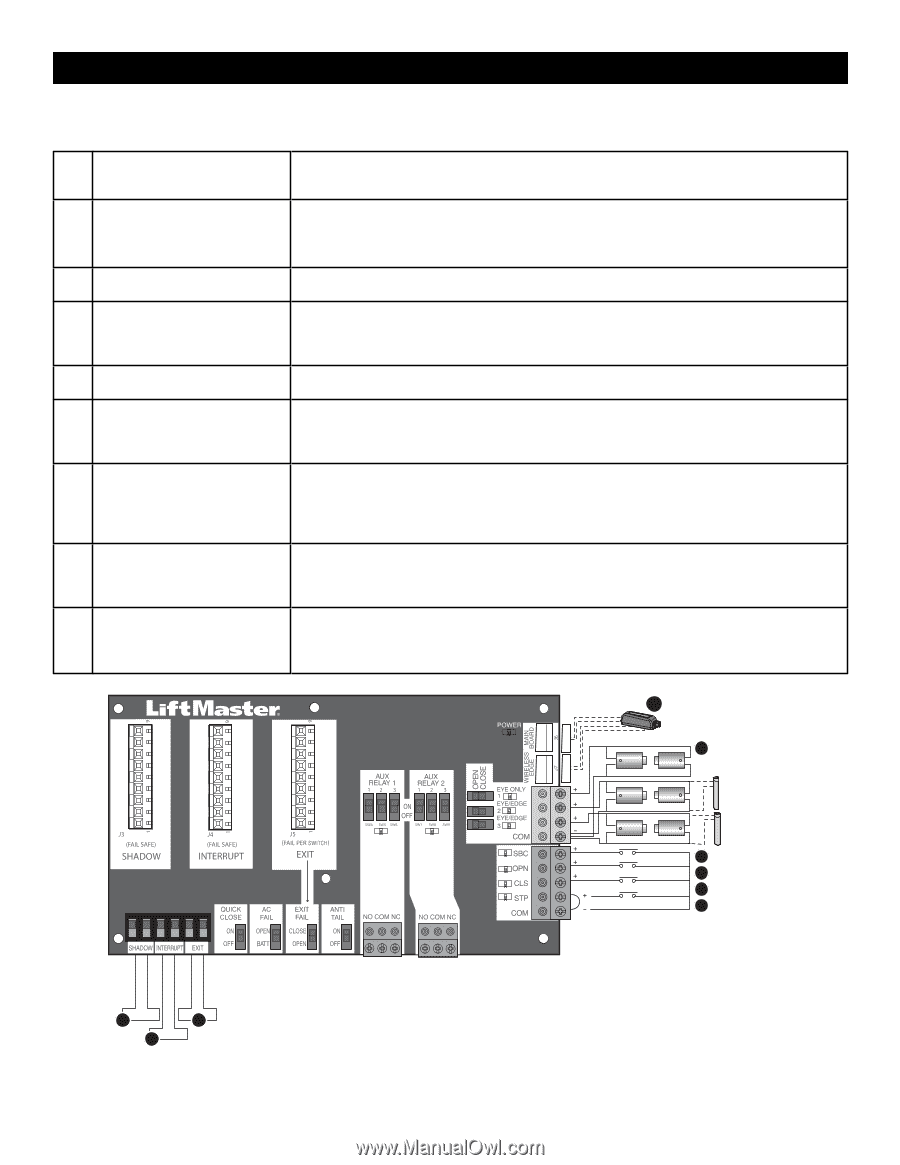
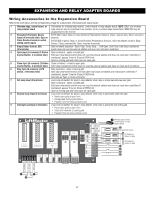
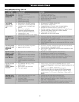
EXPANSION AND RELAY ADAPTER BOARDS Wiring Accessories to the Expansion Board Refer to the chart below and the corresponding image for a description of the expansion board inputs. 1 Wireless edge, control board, or Connection for wireless edge receiver, control board or relay adapter board. NOTE: ONLY one wireless relay adapter board edge receiver may be connected to an operator. Up to 4 wireless edge transmitters LMWETXU may be programmed to the receiver. 2 Entrapment Protection Device EYES ONLY Input: Open or Close Direction Photoelectric Sensors, Close: reverses fully, Open: reverses 4 Inputs (4 terminals total), Open or seconds. Close Direction based on switch setting next to inputs EYES/EDGE Input(s): Open or Close Direction Photoelectric Sensors, Infra-red detector wired or Edge Sensor, Close: reverses fully, Open: reverses 4 seconds. 3 Single Button Control, SBC (2 terminals) Gate command sequence - Open, Stop, Close, Stop, ... Soft Open ,Soft Close, Soft Stop (maintained switch does not override external safeties and does not reset alarm condition) 4 Open Input (& common) (3-Button Open command - opens a closed gate. Control Station, 4 terminals total) Soft open (maintained switch does not override external safeties and does not reset alarm condition) If maintained, pauses Timer-to-Close at OPEN limit. Opens a closing gate and holds open an open gate. 5 Close Input (& common) (3-Button Close command - closes an open gate. Control Station, 4 terminals total) Soft close (maintained switch does not override external safeties and does not reset alarm condition). 6 Stop Input (& common) (3-PB station, 4 terminals total) Stop command - stops a moving gate. Hard stop (maintained switch overrides Open and Close commands and resets alarm condition) If maintained, pauses Timer-to-Close at OPEN limit. Overrides an Open or Close command. 7 Exit Loop Input (2 terminals) Loop wire connection for plug-in loop detector when loop is inside secured area near gate. Open command - opens a closed gate. Soft open (maintained switch does not override external safeties and does not reset alarm condition) If maintained, pauses Timer-to-Close at OPEN limit. Opens a closing gate and holds open an open gate. 8 Shadow Loop Input (2 terminals) Loop wire connection for plug-in loop detector when loop is positioned under the gate. • Holds open gate at open limit • Disregarded during gate motion • Pauses Timer-to-Close at Open Limit 9 Interrupt Loop Input (2 terminals) Loop wire connection for plug-in loop detector when loop is along the side of the gate. • Holds open gate at open limit • Stops and reverses a closing gate • Pauses Timer-to-Close at Open Limit 1 Wireless edge receiver, control board, or relay adapter board 2 Photoelectric Sensor Photoelectric Sensor or Edge Photoelectric Sensor or Edge 3 4 5 6 Exit Loop Interrupt Loop Shadow Loop 8 7 9 37
-
 1
1 -
2
-
3
-
4
-
5
-
6
-
7
-
8
-
9
-
10
-
11
-
12
-
13
-
14
-
15
-
16
-
17
-
18
-
19
-
20
-
21
-
22
-
23
-
24
-
25
-
26
-
27
-
28
-
29
-
30
-
31
-
 32
32 -
 33
33 -
 34
34 -
 35
35 -
 36
36 -
 37
37 -
 38
38 -
 39
39 -
 40
40 -
 41
41 -
 42
42 -
43
-
44
-
45
-
46
-
47
-
48
-
49
-
50
-
51
-
52
-
53
-
54
-
55
-
56
-
57
-
58
-
59
-
60
 |
 |