LiftMaster JHDC Installation Manual - English French Spanish - Page 46
Troubleshooting continued
 |
View all LiftMaster JHDC manuals
Add to My Manuals
Save this manual to your list of manuals |
Page 46 highlights
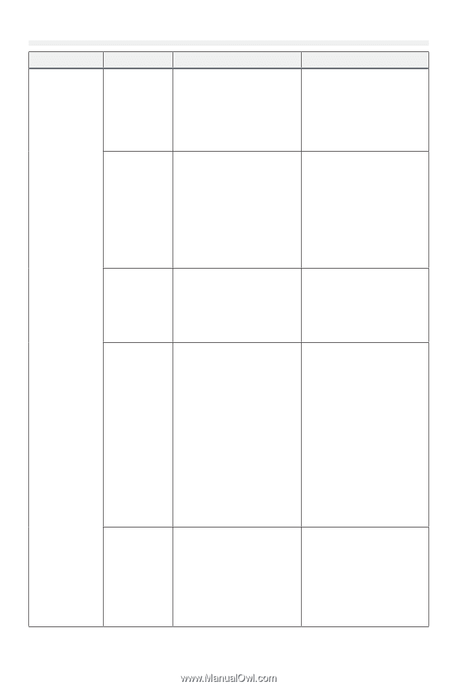
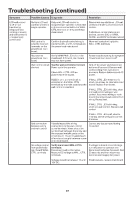
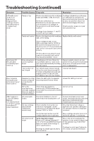
Troubleshooting (continued) Symptom Powerhead main board is off (no LEDs are lit or blinking) (continued) Possible Causes Diagnosis Resolution Faulty EMI filter board Verify EMI filter board: Perform this test only after first verifying input AC voltage. Measure AC voltage at EMI filter board output. Measure from brown wire to blue wire. [todo: check wire colors for 480V] Verify voltage is within specifications. Faulty Transformer Verify Transformer: Perform this test only after first verifying the EMI filter board. If input voltage is within specification but output voltage is outside specifications or is absent, replace the EMI filter board. If voltage is too high or too low, check that 120V/240V input voltage selection is correct. Faulty wiring or connections Faulty Rectifier Disconnect transformer output winding from rectifier(s) and measure the AC voltage across transformer output winding. Voltage should be between 22 and 35 volts AC. If voltage is out of range, see resolution. If voltage is absent: transformer has thermal protection to automatically disconnect input voltage if the transformer overheats. Allow transformer to cool if it is hot, and then re-test. If transformer is cool and voltage is still absent, replace the transformer. Inspect all connections and wiring Correct any issues found with wiring from EMI filter board, transformer, or connections. rectifiers, and DC IN terminals on the main board. Ensure there are no loose connections, cut wires, broken insulation, etc. Verify wiring matches wiring diagram. Verify Rectifier: If the transformer and all wiring is verified but DC voltage is still not present at the main board DC IN terminals, the rectifiers are most likely faulty. If an electrical meter with a diode test function is available, each of the 4 diodes internal to the bridge rectifiers may be checked using the diode check functionality: 1) check each diode in the forward direction and verify they conduct with ~ 1V drop or less Replace faulty rectifier(s). Rectifier mounting screws must be tight enough to ensure good thermal contact with the chassis through the thermal interface pad. However, the rectifier screw must not be too tight or it could be damaged. [torque spec here, even?] Interface between the rectifier and the chassis should be clean of any foreign substances before a new rectifier is installed. 2) check each diode in the reverse direction and verify they do not conduct (meter will read the same as disconnected leads) Short or overload in device connected to main board Turn off power and disconnect batteries from main board. Disconnect all cabling from main board except for main power. If any device is found to cause an issue, the device may be faulty and should be repaired or replaced as necessary. Restore power and verify LEDs light. Reconnect wiring to main board one device at a time testing to see if any device causes the main board to fail to light LEDs. 46
-
 1
1 -
2
-
3
-
4
-
5
-
6
-
7
-
8
-
9
-
10
-
11
-
12
-
13
-
14
-
15
-
16
-
17
-
18
-
19
-
20
-
21
-
22
-
23
-
24
-
25
-
26
-
27
-
28
-
29
-
30
-
31
-
32
-
33
-
34
-
35
-
36
-
37
-
38
-
39
-
40
-
 41
41 -
 42
42 -
 43
43 -
 44
44 -
 45
45 -
 46
46 -
 47
47 -
 48
48 -
 49
49 -
 50
50 -
 51
51 -
52
-
53
-
54
-
55
-
56
-
57
-
58
-
59
-
60
-
61
-
62
-
63
-
64
-
65
-
66
-
67
-
68
-
69
-
70
-
71
-
72
-
73
-
74
-
75
-
76
-
77
-
78
-
79
-
80
-
81
-
82
-
83
-
84
-
85
-
86
-
87
-
88
-
89
-
90
-
91
-
92
-
93
-
94
-
95
-
96
-
97
-
98
-
99
-
100
-
101
-
102
-
103
-
104
-
105
-
106
-
107
-
108
-
109
-
110
-
111
-
112
-
113
-
114
-
115
-
116
-
117
-
118
-
119
-
120
-
121
-
122
-
123
-
124
-
125
-
126
-
127
-
128
-
129
-
130
-
131
-
132
-
133
-
134
-
135
-
136
-
137
-
138
-
139
-
140
-
141
-
142
-
143
-
144
-
145
-
146
-
147
-
148
-
149
-
150
-
151
-
152
-
153
-
154
-
155
-
156
-
157
-
158
-
159
-
160
-
161
-
162
-
163
-
164
-
165
-
166
-
167
-
168
-
169
-
170
-
171
-
172
-
173
-
174
-
175
-
176
-
177
-
178
-
179
-
180
-
181
-
182
-
183
-
184
-
185
-
186
-
187
-
188
-
189
-
190
-
191
-
192
-
193
-
194
-
195
-
196
-
197
-
198
-
199
-
200
-
201
-
202
-
203
-
204
-
205
-
206
-
207
-
208
-
209
-
210
-
211
-
212
-
213
-
214
-
215
-
216
 |
 |