LiftMaster LA400 LA400 Push to Open Addendum Manual - Page 2
Battery Replacement, - gate opener
 |
UPC - 753182403953
View all LiftMaster LA400 manuals
Add to My Manuals
Save this manual to your list of manuals |
Page 2 highlights
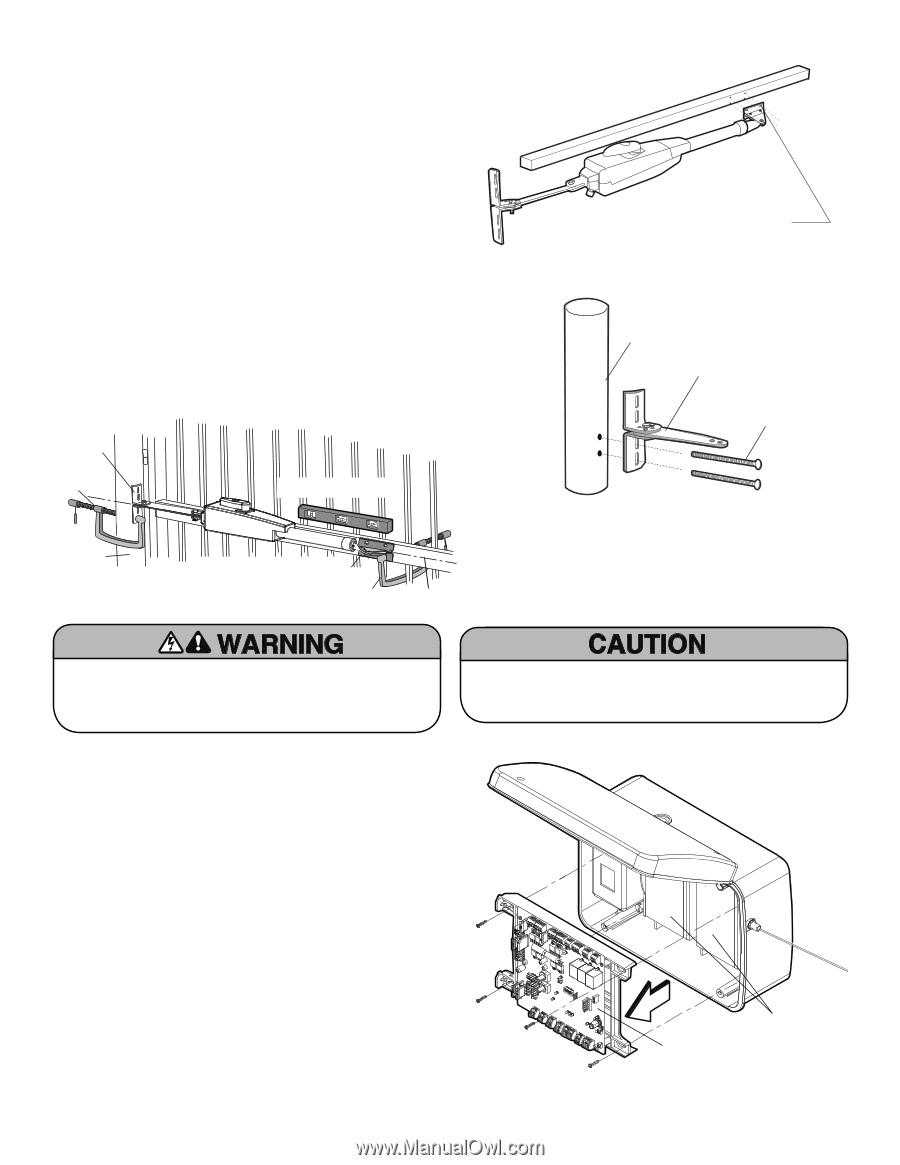
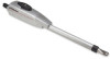
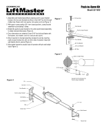
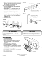
7. With gate open and operator in retracted position, clamp bracket to cross member, using C clamp. Adjust operator until assembly is level. Tighten in place at this time (Figures 4 & 6). NOTE: All four mounting holes must be used. 8. Once brackets are clamped in place, remove clevis pins and washers to detach operator. 9. Mark reference points for bolt holes on fence posts and cross member. Be sure to mark holes in the vertical center of post bracket slots (Figure 5). 10. Remove brackets from gate post and cross member. 11. Drill 13/32" holes in marked locations for gate post and 11/32" for gate bracket. 12. Secure post bracket assembly to gate post with 3/8"-16 x 6" carriage bolts, flat washers, lock washers and nuts. Secure gate bracket to cross member with 5/16" carriage bolts, flat washers, lock washers and nuts. 13. Reattach operator to gate. Figure 4 Figure 5 Figure 6 Post Bracket Assembly C Clamp Operator MUST be level Fence Post Gate in OPEN Position Gate Bracket C Clamp Gate in Open Position LEVEL Horizontal Cross Member Mark cross member through middle of gate bracket slots and drill 11/32" holes Mark fence post through middle of bracket slots and drill 13/32" holes Post Bracket Assembly 3/8"-16 x 6" Carriage Bolt To avoid SERIOUS personal INJURY or DEATH from electrocution, DISCONNECT electrical power to operator BEFORE proceeding. To reduce the risk of FIRE or INJURY to persons use ONLY Chamberlain part #K74-30762 for replacement batteries. BATTERY REPLACEMENT 1. Disconnect power to operator. 2. Open the control box cover. 3. Remove all quick connect terminals in use to the control board. Remember location of all wire connections for reinstallation. 4. Remove control board and mounting plate. 5. Disconnect terminals leads to both batteries. 6. Replace both batteries and connect red wires to the positive (+) terminals (red). Connect black wires to the negative (-) terminals (black). 7. Install control board and mounting plate. 8. Reconnect all quick connect terminals to the control board. 9. Close cover of control box. 10. Reconnect power to operator. Control Board and Mounting Plate Batteries 01-32479B © 2008, The Chamberlain Group, Inc. All Rights Reserved
-
 1
1 -
 2
2
 |
 |